7
Section 1 Assembly and Setup
11/16/00
RC35120 RCM35120 Rotary Cutter 312-301M
Land Pride
Section 1
Assembly and Setup
Tractor Requirements
The lift-type cutter is designed with a category II hitch.
Both Lift and Pull-Type Cutters are designed for tractors
with a minimum PTO horsepower rating of 50 HP and
maximum of 120 HP. Adequate front end weight is re-
quired on tractors for use with lift-type cutter.
Lift-Type Cutter
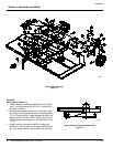
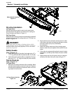
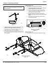
Refer to Figure 1-1:
Hitch & Axle Assembly
1. Assemble hitch straps (#1) to inside of lower hitch an-
gles welded to cutter deck with 1 1/8" hitch pin (#2)
lock washers (#3) and nuts (#4).
2. Install pivoting upper hitch (#5) to inside of hitch straps
with hitch braces (#6) on the outside. Do not attach
other end of hitch braces at this time. Install 1" x 6 1/2"
long bolt (#7) and lock nut (#8). Do not tighten bolts at
this time.
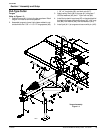
3. Attach axle assembly (#9) to rear of cutter:
a. Position axle as shown.
b. Attach axle on the right hand side of cutter with
cylinder pivot lug (#10) and 1 1/2" x 1" x 1 7/8"
long spacer (#11) on outboard side of pivot, and 1
NOTE: Do not tighten hardware until assembly is
complete.
1/2" x 1" x 1 1/8" long spacer (#12) and hitch brace
(#6) on inboard side of pivot. Secure with a 1" x
9 1/2" long bolt (#13), flat washer (#14), and lock
nut (#8).
c. Attach axle on the left hand side of cutter with
1 1/2" x 1" x 1 1/8" long spacer (#12) on both sides
of pivot attach hitch brace (#6) on inboard side of
pivot. Secure with a 1" x 9" long bolt (#15), flat
washer (#14), and lock nut (#8)
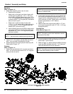
d. Install outboard axle mounts (#33) to deck mount-
ed support (#34) with pivot shaft pin (#35) and se-
cure with 1/4” -20 x 1 1/2” long hex bolt (#36) and
lock nut (#37).
e. Fasteners for hitch straps (#1) and pivoting upper
hitch (#5) can now be tightened. Do not over tight-
en 1" x 6 1/2" long upper hitch bolt (#7). Upper
hitch must be free to pivot.
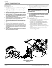
4. If cutter is equipped with ratchet height adjustment:
f. Install ratchet (#16) and secure with pins and clips
furnished with ratchet.
5. If cutter is equipped with hydraulic height adjustment:
g. Install 3 1/2" x 8" hydraulic cylinder (#17) and se-
cure with 1" pins and clips furnished with cylinder.
NOTE: 1" bolts should be installed pointing outboard.


