


11
Section 1 Assembly and Setup
11/16/00
RC35120 RCM35120 Rotary Cutter 312-301M
Land Pride
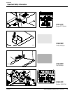
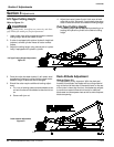
Safety Guards Assembly
Figure 1-5
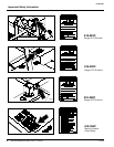
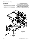
2. Align lower link arms of tractor to hitch pins on cutter.
Insert lower hitch pins into lower ball swivels on tractor
and secure with lynch pins (furnished by
the customer).
3. Adjust and attach tractor top link to pivoting upper
hitch on cutter with pin supplied. Secure with hair pin
cotter.
4. If the cutter is equipped with optional hydraulic height
adjustment, connect cylinder hoses to tractor remote
outlets.
5. Adjust tractor top link until upper hitch pin is aligned
vertically with lower hitch pins, refer to Figure 1-7.
14259
14261
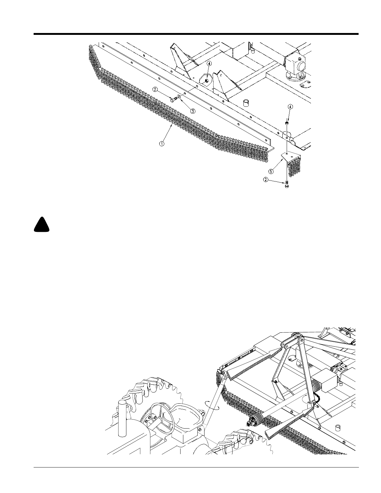
Lift-Type Tractor Hook-Up
Figure 1-6
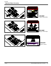
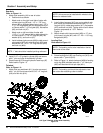
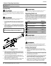
Driveline Installation
Lift-Type Cutter
Slide the driveline end with the slip clutch device over
splined shaft of the gearbox and secure with locking de-
vice of driveline, as shown in Figure 1-1.
Pull-Type Cutter
Attach constant velocity driveline to stub shaft on jackshaft
driveline and secure with locking device of PTO shaft, as
shown in Figure 1-3.
!
DANGER!
Rotary cutters have the ability to discharge objects at high
speeds; therefore, the use of front safety shields is strongly rec-
ommended when cutting along highways or in an area where
people may be present.
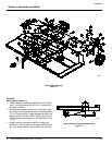
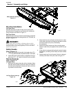
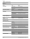
Safety Guards
Refer to Figure 1-5:
1. Install chain guard (#1) to cutter front angle using 1/2” x
1 1/2” long hex bolts (#2), flat washers (#3), & nuts (#4).
2. Install side chain mounts (#5) to underside of front an-
gle using 1/2” 1 1/2” long hex bolts (#2) and nuts (#3).
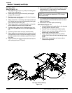
Tractor Hook-Up
Refer to Figure 1-6:
Lift-Type Cutter
1. Be certain that tractor draw bar will not interfere. Move
draw bar ahead, aside or remove if required. Draw bar
should also be checked for clearance when unit is be-
ing raised for the first time.