8
Section 1 Assembly and Setup
RC35120 RCM35120 Rotary Cutter 312-301M
11/16/00
Land Pride
Tailwheel
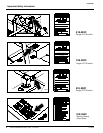
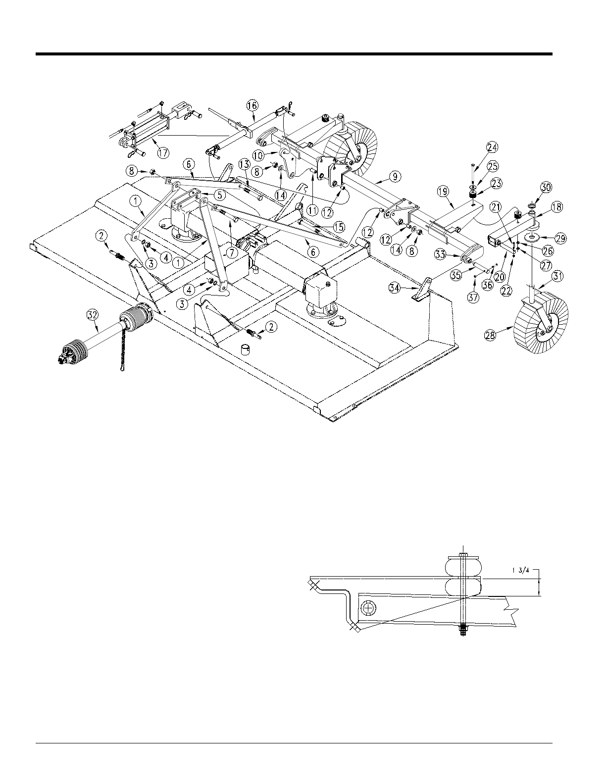
Refer back to Figure 1-1:
1. Attach caster arm weldment (#18) to axle arm (#19)
with 1” pin (#20) secure with 5/16” x 2” long bolt (#21)
and lock nut (#22).
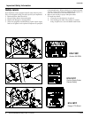
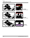
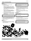
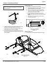
2. Install rubber bumpers (#23) one on top side of axle
arm mount and one below as shown and secure with
1/2” x 8” long bolt (#24), rubber stop washer (#25), flat
washer (#26), and lock nut (#27). Tighten lock nut until
rubber bumper compresses to 1 3/4” as shown in Fig-
ure 1-2.
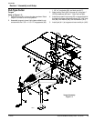
3. Attach tailwheel yoke spindle (#28) to caster arm
weldment (#18) and secure with washer (#29) on bot-
tom and washer (#30) on top and spiral roll pin (#31).
Rubber Bumper Tightening Dimensions
Figure 1-2
10440
14256
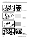
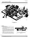
Hitch & Axle Assembly
Figure 1-1


