


14
Section 1: Assembly and Set-up
AFM4214 and AFM4216 All-Flex Grooming Mowers 315-587M
11/14/08
Land Pride
Table of Contents
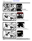
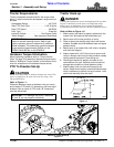
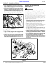
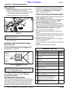
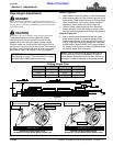
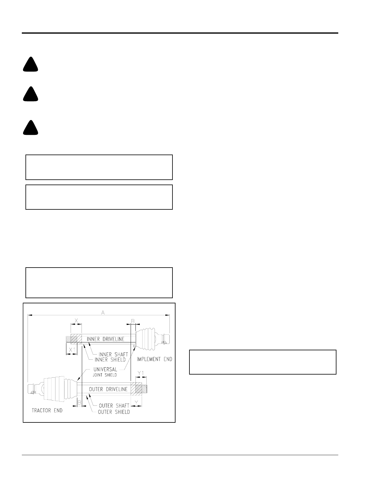
Refer to Figure 1-3
1. Place tractor gear selector in park, shut tractor
engine off, set park brake and remove switch key.
2. Attach driveline to mower and tractor as follows:
a. Slide inner yoke of driveline over mower gearbox
shaft and secure with locking collar.
b. Slide outer yoke with constant velocity joint over
tractor PTO shaft and secure with locking collar.
c. Skip to Step 4 if driveline fits between tractor and
Grooming Mower.
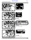
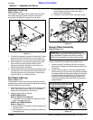
3. The driveline will require shortening if it is too long to
fit between the tractor and Grooming Mower.
Shorten driveline as follows:
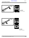
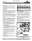
a. Pull driveline profiles apart into two sections as
shown in Figure 1-3.
b. Attach outer driveline universal joint to tractor
PTO shaft and inner driveline universal joint to
gearbox shaft. Pull on each driveline section to be
sure universal joints are secured.
c. Hold driveline sections parallel to each other to
determine if they are too long. The inner and outer
shields on each section should endapproximately
1" short of reaching the universal joint shield on
the adjacent section (see “B” dimension). If they
are too long, measure 1" (“B” dimension) back
from the universal joint shield and make a mark at
this location on the inner and outer shields.
d. Cut off inner shield at mark (“X” dimension). Cut
same amount off inner shaft (“X1” dimension).
Repeat cut off procedure (“Y”&“Y1” dimensions)
to cut outer driveline half.
e. Remove all burrs and cuttings.
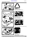
4. With driveline profiles pulled apart, apply
multi-purpose grease to the inside of the outer profile
and then reassemble the two profiles.
5. Attach inner driveline yoke to gearbox shaft and
outer driveline yoke to tractor's PTO shaft.
6. The driveline should now be moved back and forth to
insure that both ends are secured. Reattach any end
that is loose.
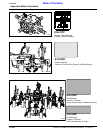
7. Hook a safety chain in the hole on the outer driveline
yoke shield and its opposite end to the tractor.
8. Hook the other safety chain in the hole on the inner
driveline yoke shield and its opposite end to the
mower.
IMPORTANT: Two small chains supplied with the
driveline must be attached to restrict driveline shield
rotation.
Main Driveline Installation
!
WARNING
Damaged drivelines can cause serious injury or death.
!
CAUTION
Tractor PTO shield and all Grooming Mower guards must be
in place at all times during operation!
!
CAUTION
Always engage parking brake, shut off tractor and remove key
before dismounting from tractor.
Always engage PTO at low engine rpm to minimize
start-up torque on driveline. Drivelines with friction
clutches must go through a “run-in” operation prior
to initial use and after long periods of inactivity. See
“Driveline Protection” on page 27” for a detailed run-in
description.
Check Constant Velocity Driveline Length
Driveline Shortening
Figure 1-3
IMPORTANT: The driveline must be lubricated before
putting it into service. Refer to “Lubrication Points” on
page 31.
IMPORTANT: Some tractors are equipped with
multispeed PTO ranges. Be certain your tractor ‘s
PTO is set for 540 rpm.
IMPORTANT: Always check driveline length during
initial setup and when connecting to a different tractor.
Too long a driveline can damage tractor, gearbox and
the driveline.
23557