


13
Section 1: Assembly and Set-up
11/14/08
AFM4214 and AFM4216 All-Flex Grooming Mowers 315-587M
Land Pride
Table of Contents
Section 1: Assembly and Set-up
Tractor Requirements
Tractor horsepower should be within the range noted
below. Tractors outside the horsepower range must not
be used.
Horsepower Rating. . . . . . . . . . . . . . . . . . . .40-70 HP
Rear PTO Shaft Type . . . . . . . . . . . . . .1 3/8”-6 Spline
Rear PTO Speed . . . . . . . . . . . . . . . . . . . . 540 RPM
Hitch Type . . . . . . . . . . . . . . . . . . . . . . . . . .Draw Bar
Hydraulic Outlets . . . . . . . . . . . . . One Duplex Outlet
Tractor Weight . . . . . . . . . See Important Note Below
Hardware Torque Information
When tightening hardware, refer to “Torque Values
Chart” on page 43 to determine standard torque values.
Refer to "Additional Torque Values" at the bottom of the
chart for exceptions to the standard torque values.
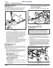
PTO To Drawbar Set-Up
!
CAUTION
Do not over speed PTO or machine damage may result. This
mower is designed to be used with a tractor using a rear
540 rpm PTO drive.
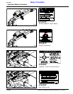
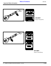
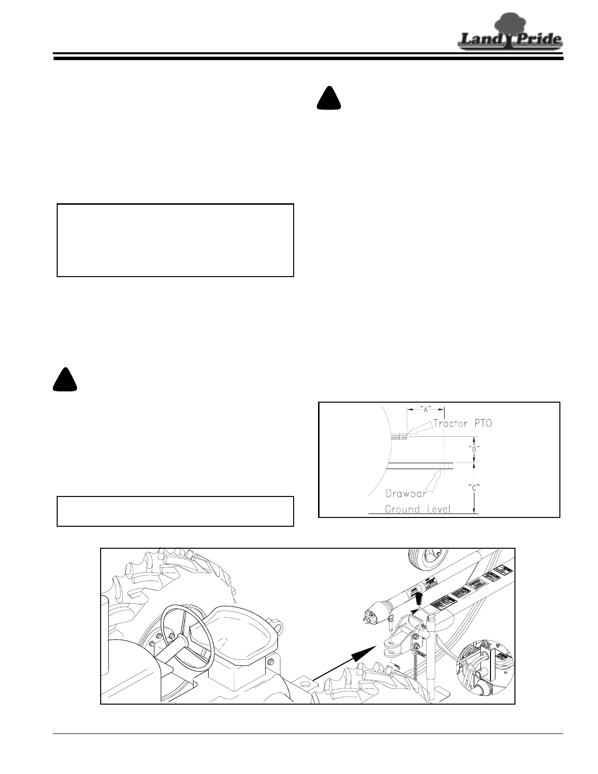
Refer to Figure 1-1:
Distances between center of drawbar hitch pin hole to
end of tractor PTO shaft (“A” dimension) and from top of
drawbar hitch to center of PTO shaft (“B” dimension)
must be maintained.
IMPORTANT: Ballast may need to be added to your
tractor to maintain steering control. Refer to your
tractor’s operator manual to determine if additional
ballast is needed. This mower has a positive transport
tongue weight of approximately 540 lbs. on the
AFM4214 and 580 lbs. on the AFM4216.
IMPORTANT: PTO damage may occur if distances
“A” and “B” are not properly maintained.
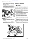
Tractor Hook-up
!
DANGER
Crushing Hazard between tractor and implement. Do not allow
anyone to stand between the tractor and implement while
backing-up to an implement. Never operate the hydraulic
3-point lift controls while someone is directly behind the tractor.
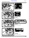
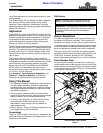
Refer to Refer to Figure 1-2:
1. Make certain jack stand is properly attached to the
mower hitch and secured with attachment pin.
2. Back tractor within close proximity of clevis.
3. Raise or lower jack stand to align clevis with tractor
drawbar. Drawbar should fit between lower and upper
plates of clevis.
4. Back tractor up to mower hitch until holes in drawbar
and clevis are aligned.
5. Attach mower with a 3/4" hitch pin and secure with
lock pin. Always use a hitch pin that contains a safety
locking device to prevent it from falling out.
6. Retract jack stand until weight of mower is fully
removed from the jack. Remove jack and store on
storage tube located on divider gearbox shield.
7. Attach safety chain on the frame tongue to the
tractor. Adjust chain length to remove all slack except
what is necessary to permit turning of mower. Lock
chain hook securely onto the chain.
PTO to Drawbar Distances
Figure 1-1
22273
= 8”
= 14”
Mower to Tractor Hook-up
Figure 1-2
14918