


5
3/20/07
Manual No. 700-520M
Assembly Instructions
Land Pride
■
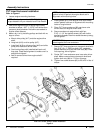
Assembly of CVT Pulley and Belt
Refer to Figure 4:
1. Make a dry run by installing driven pulley (#18) onto
trans-axle input shaft until it stops and then spin
pulley by hand to verify it does not catch on any
objects while rotating. Remove pulley.
2. Make certain shims in step 3e on page 4 are still on
the engine shaft.
3. Apply anti-seize to engine drive shaft and install
3/16" x 1/4" x 2 1/4" long key (#4).
4. Slide drive pulley (#17) onto engine drive shaft and
hang belt (#16) on drive pulley (#17).
5. Apply anti-seize to trans-axle input shaft and Install
3/16" sq. x 3" long key (#3).
6. Install belt (#16) on driven pulley (#18) and slide
pulley onto trans-axle driven shaft.
7. Push both pulleys with installed belt back until they
stop. Recheck belt alignment.
8. Secure drive pulley (#17) with 3/8"-24 x 6 1/2" GR5
hex bolt (#8), 3/8" lock washer (#11) and flat
washer (#10). Torque hex bolt to 35 ft. lbs.
9. Secure driven pulley (#18) with 1/2"-20 x 1 3/4" hex
bolt (#6), 1/2" lock washer (#12) and 1/2" flat
washer (#13). Torque hex bolt to 85 ft. lbs.
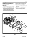
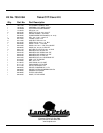
Outer CVT Enclosure Installation
Figure 5
Assembly of CVT Outer Enclosure
Refer to Figure 5:
1. Being careful not to scratch gasket edge of outer
enclosure (#7), mate enclosure with inner enclosure
IMPORTANT: Pulley flanges will bend and nick easily
if handled roughly. Always handle pulleys gently to
prevent damage.
and securewith twelve 1/4"-20 x3/4" screws (#4).Do
not tightenuntil allscrews areinstalled. Tighteneach
screw to 5.6 ft-lbs. of torque.
2. Install drain cap (#6) over drain nozzle and secure
with 1" spring clamp (#3).
3. Install CVT diverter outlet (#8) to outer enclosure
with two 3/16” pop rivets (#2).
4. Install exhaust heat shield (#10) to exhaust pipe.
Secure with existing #8 x 1/2” hex screws (#5) and
tighten.
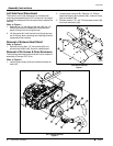
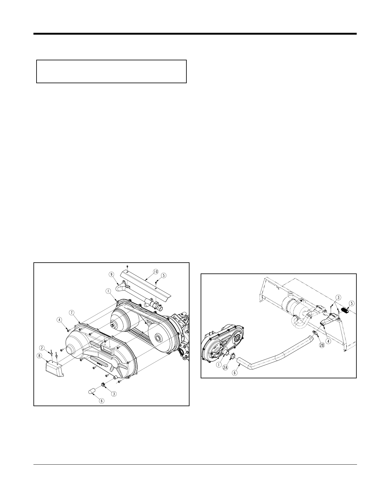
Assembly of CVT Venting
Refer to Figure 6:
1. Slip worm drive hose clamp (#2A) over bottom end of
air intake hose (#6). Do not tighten. Install air intake
hose over CVT inner enclosure opening (#1).
1. Slip second worm drive hose clamp (#2B) over top
end of air intake hose (#6). Do not tighten.
2. Insert snorkel (#4) into open end of air intake
hose (#6) and position snorkel on top of Treker
firewall panel as shown.
3. Mark hole locations for mounting snorkel andpre drill
two 1/8" diameter holes in fire wall panel flange.
4. Secure snorkel to firewall panel by driving two
#10 x 3/4” hex head self-tapping drive screws (#4)
into the panel’s flange.
5. Position worm drive clamps (#2A & #2B)
approximately 1/8" from each end of air intake hose
and tighten.
6. Insert air intake filter (#5) into snorkel (#4).
CVT Venting Installation
Figure 6
Final Assembly
Refer to Figure 1 on page 2:
1. Reattach side panel (#1) with five 1/4” Phillip head
machine screws (#2) and 1/4” hex flange lock nuts
(#3). Tighten lock nuts to 6 ft. lbs. of torque.
2. Remove blocking supporting Treker bed in the up
position and lower the bed.