


4
Manual No. 700-520M 3/20/07
Land Pride
Assembly Instructions
■
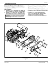
Inner CVT Shield, Pulleys & Belt Installation
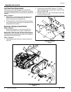
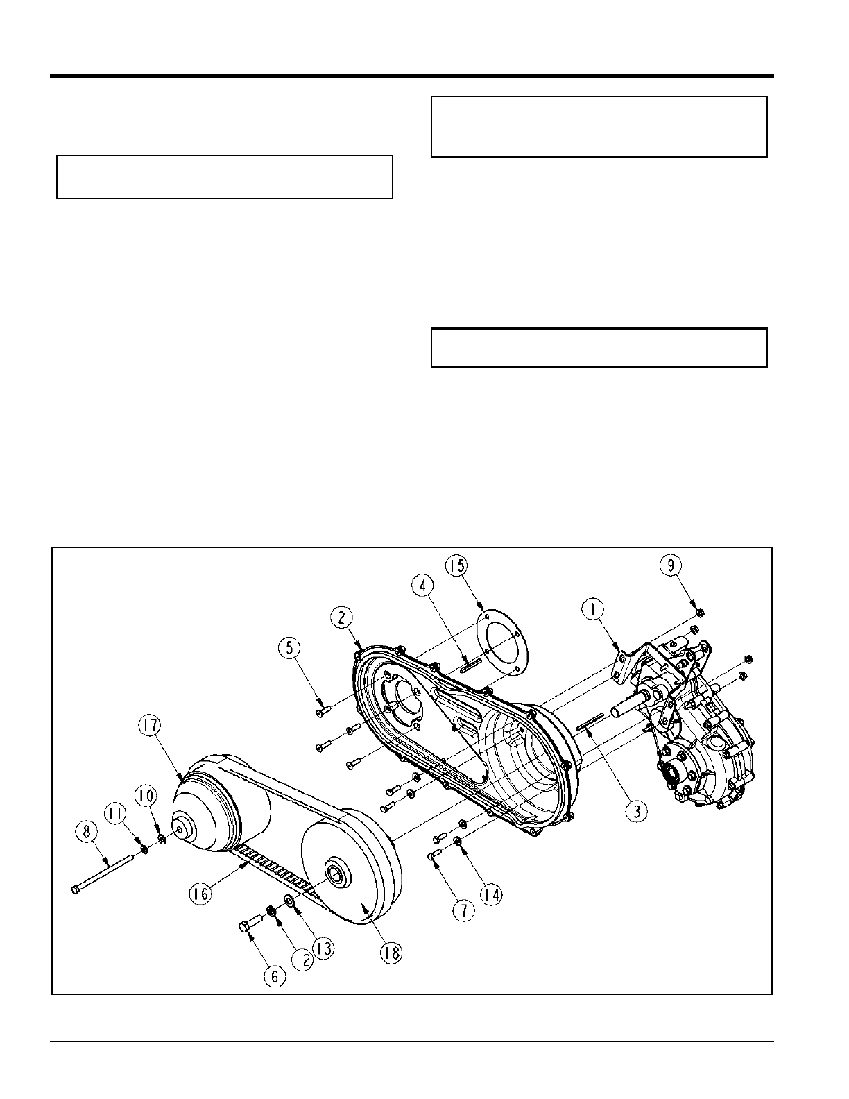
Figure 4
CVT Inner Enclosure Installation
Refer to Figure 4:
1. Loosen engine mounting hardware.
2. Use clutch alignment tool to adjust engine shaft
shoulder to offset 1.937" (1 15/16") out farther than
trans-axle shaft shoulder. Add shims as needed to
finalize offset distance.
3. Make a dry run by installing pulleys and belt with no
keys or shims.
a. Mount drive pulley (#17) onto the engine drive
shaft.
b. Hang belt (#16) on drive pulley (#17).
c. Install belt (#16) on driven pulley (#18) and slide
pulley onto trans-axle driven shaft.
d. Push both pulleys with installed belt back until
they stop. Check belt alignment to make sure it is
straight and aligned.
e. Add or remove shims from engine shaft if
required.
NOTE: Clutch alignment tool (P/N 790-001A) may
be purchased from your nearest Land Pride Dealer.
4. Install gasket (#15) over engine drive shaft. Make
certain gasket holes are in alignment with mounting
holes on engine block.
5. Place CVT inner enclosure (#2) over trans-axle
driven shaft and engine driven shaft.
6. Secure enclosure to engine block with four
5/16" x 1 1/4" hex socket screws (#5) with loctite
applied to threads. Draw hex socket screws up snug;
do not tighten.
7. Secure CVT inner enclosure to trans-axle shaft with
four 5/16"-18 x 1" GR5 hex bolts (#7), neoprene
plated washers (#14) and hex lock nuts (#9). Draw
nuts up snug; do not tighten.
8. Center CVT inner enclosure over trans-axle driven
shaft. Make sure enclosure clears axle shaft and
tighten lock nuts (#9) to 17 ft.lbs. of torque.
9. Tighten hex socket screws (#5) to 20 to 25 in-lbs. of
torque.
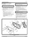
NOTE: A thin layer of silicon can be added to the
gasket to hold it against the engine block and in
alignment with mounting holes.
IMPORTANT: Neoprene on washers (#14) in step 7 is
placed against the inner enclosure.