15
Section 1: Assembly & Set-up
12/15/15
RCF2784 Rotary Cutters 326-364M
Table of Contents
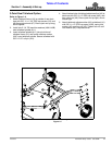
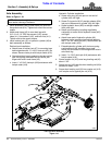
Trail-Type Tongue Assembly
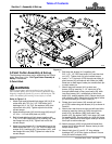
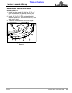
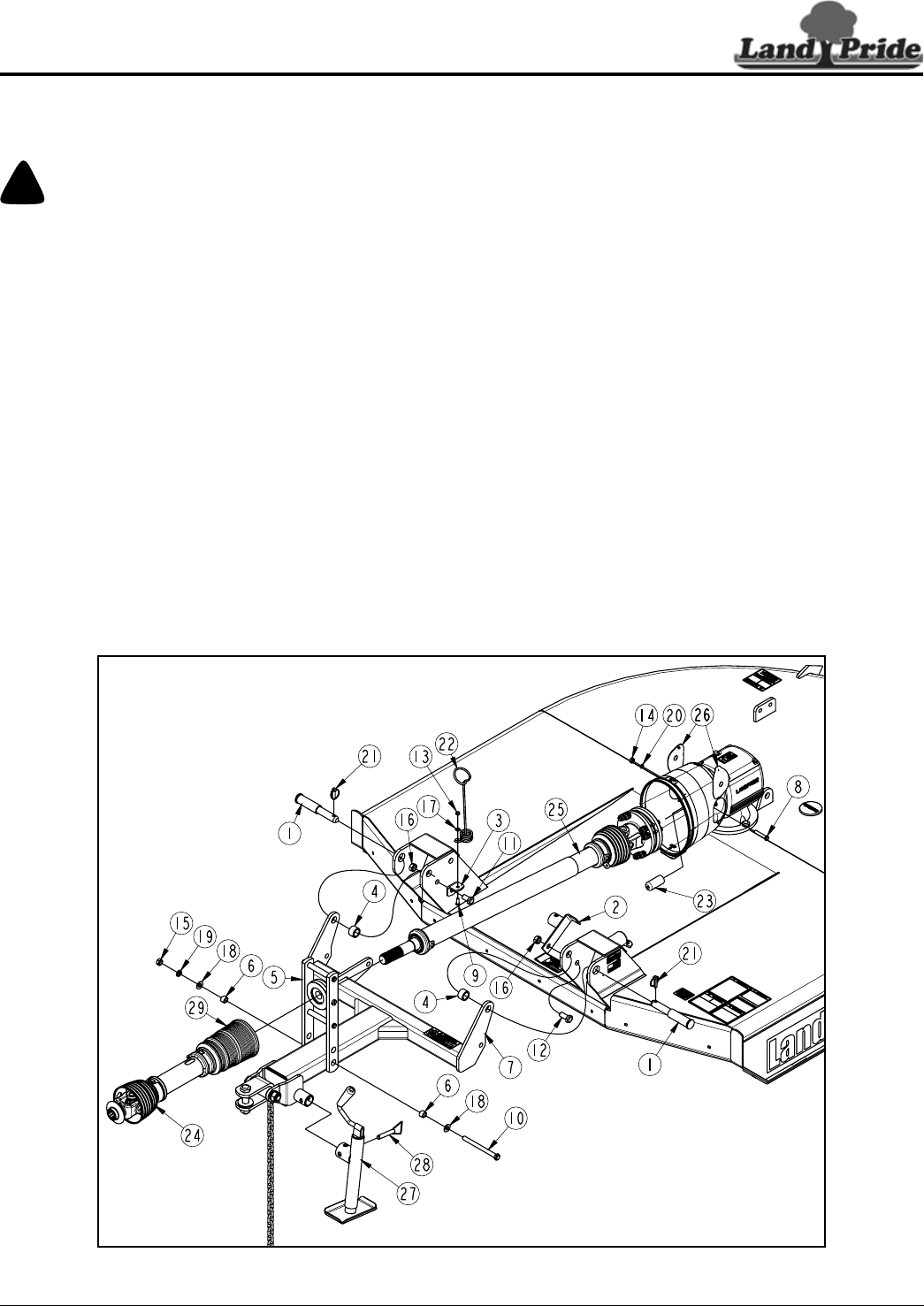
Figure 1-9
33268
5. Secure driveline (#25) to gearbox input shaft with
coupling bolt (#8), spring lock washer (#20), and hex
nut (#14). Tighten hex nut to the correct torque.
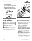
6. Move slip-clutch back and forth several times to
make certain it is locked onto the gearbox shaft.
7. Rotate access doors (#26) closed and snap in place.
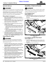
8. Insert jackshaft end of driveline (#25) through
bearing in bearing support assembly (#5).
9. Pull bearing in bearing support assembly (#5)
against driveline (#25) and tighten set screw in
bearing collar against driveline jackshaft.
10. Attach driveline (#24) to jackshaft on driveline (#25)
by pulling back on pull collar (#29) and pushing yoke
onto the jackshaft. Release pull collar and continue
to push yoke forward until pull collar locks in place.
11. Move driveline yoke back and forth several times to
make sure yoke is locked in place.
Driveline Installation
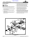
Refer to Figure 1-9:
!
WARNING
Do not use a PTO adapter. A PTO adapter will increase strain
on the tractor’s PTO shaft resulting in possible damage to
shaft and driveline. It will also defeat the purpose of the
tractor’s master shield and could cause bodily injury or death.
1. Remove rubber protective sleeve (#23) from gearbox
input shaft and discard.
2. Remove coupling bolt (#8) from end of slip-clutch.
3. Unsnap one end of both access doors (#26) and
rotate doors open.
4. Slide slip-clutch end of driveline onto gearbox input
shaft until holes in slip-clutch align with notch in
gearbox input shaft.


