10
Section 1: Assembly & Set-up
Model SBR48, SBR60 & SBR72 Seed Bed Roller 322-215M
2/23/09
Land Pride
Table of Contents
Pull-type Hook-up
!
DANGER
Crushing Hazard between tractor and implement. Do not
allow anyone to stand between the tractor and implement
while backing-up to an implement.
!
DANGER
Engage parking brake, shut off tractor and remove key before
dismounting from the tractor.
!
WARNING
The Seed Bed Roller hitch has negative weight.
!
WARNING
See Figure 3-5 on page 15. Chock front and back of roller
when using support stand to prevent unit from rolling and
causing property damage and/or bodily injury.
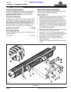
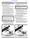
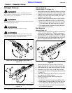
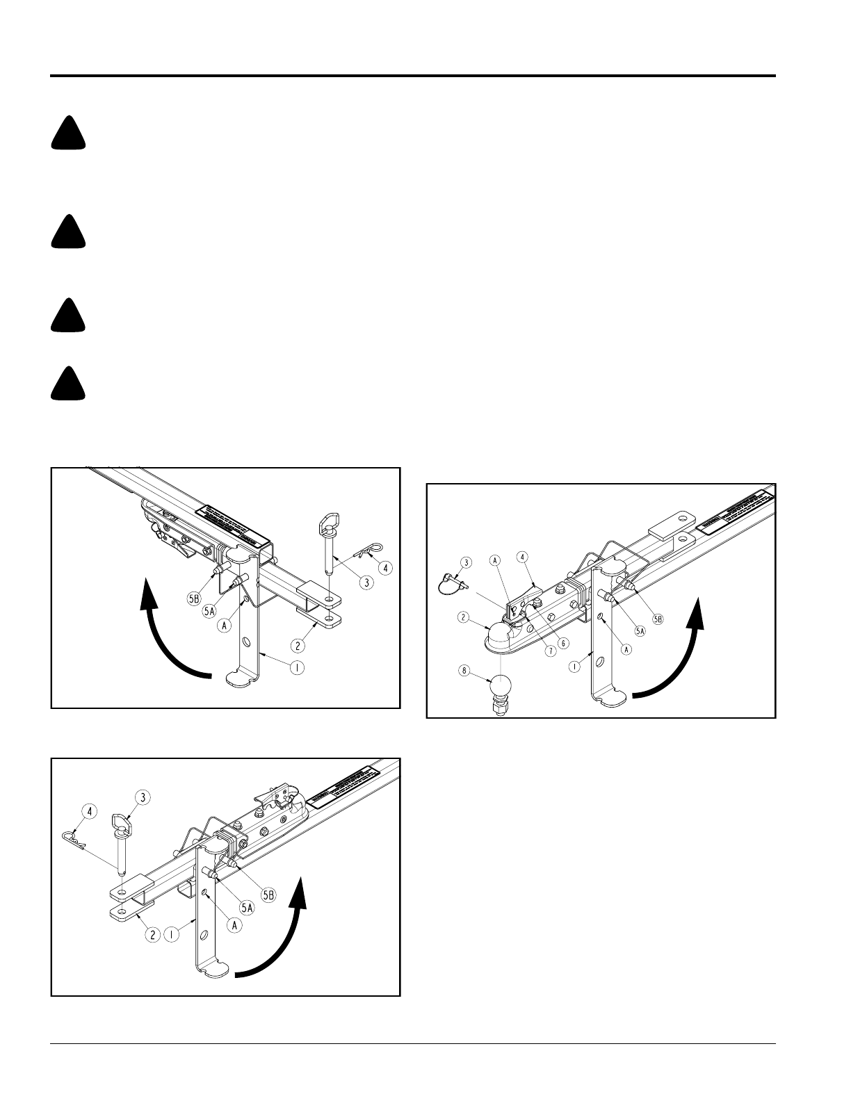
Clevis Hook-up (Tractor drawbar height under 13")
Figure 1-7
Clevis Hook-up (Tractor drawbar height 13" and higher)
Figure 1-8
25799
25783
Clevis Hook-up
Refer to Figure 1-7 & Figure 1-8:
1. Back machine up to the Seed Bed Roller until hole in
drawbar hitch is aligned with holes in the clevis hitch.
2. Dismount machine properly and insert hitch pin (#3)
through hitch clevis holes and drawbar hitch hole.
Install hair pin cotter (#4).
3. Without removing wire snap lock pins (#5A & #5B):
• Unhook wire retainers for both pins (#5A & #5B).
• Rotate bottom of support stand (#1) back until hole
“A” is in alignment with wire snap lock pin (#5B).
• Push support stand onto both wire snap lock pins
and re-hook wire retainers.
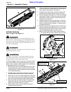
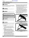
Ball Hook-up
Refer to Figure 1-9:
1. Attach customer supplied 2" ball (#8) to the machine
pulling the Seed Bed Roller. Tighten nut supplied
with the ball to correct torque. 2" Ball with 3/4" shank
(P/N 890-975C) can be purchased from Land Pride.
2. Back machine up to the Seed Bed Roller until the 2"
ball is in alignment with ball socket in hitch (#2).
Ball Hook-up (Drawbar height 13" and higher)
Figure 1-9
3. Remove retaining pin (#3), pull up on lock latch
trigger (#6) and then pull up on release handle (#4).
4. With handle (#4) up, lower hitch (#2) over 2" ball (#8).
5. Make sure hitch (#2) is fully on ball (#8) and then
push handle (#4) down until lock latch (#6) is secured
in notch (#7).
6. Insert wire retaining pin (#3) in hole “A” and secure
pin in place with its wire retainer.
7. Without removing the two front wire snap lock
pins (#5A & #5B):
• Unhook wire retainers for both pins (#5A & #5B).
• Rotate bottom of support stand (#1) back until hole
“A” is in alignment with wire snap lock pin (#5B).
• Push support stand onto both wire snap lock pins
and re-hook wire retainers.
25776


