


18 –English
INSTALLATION
FIG. 28
FIG. 29
FIG. 31
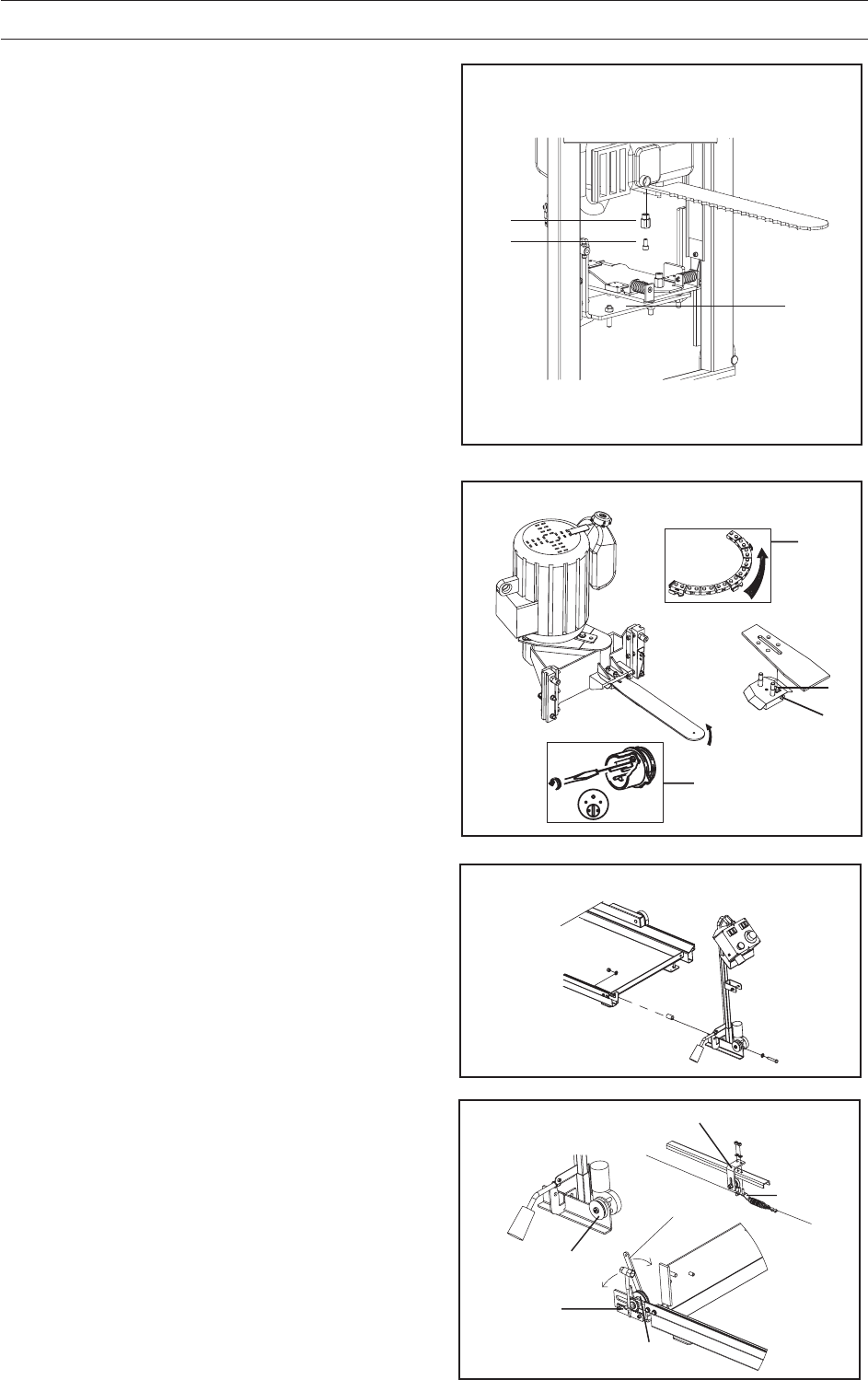
FIG. 30
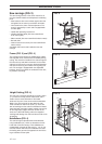
One-man sawmill with chain saw
engine
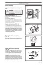
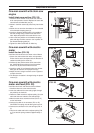
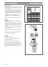
Install chain saw and bar (FIG. 28)
1.Install the chain and bar on the chain saw, see the
chain saw operator’s manual. Replace the saw’s bar
nuts with two extended bar nuts (A).
2.Screw in the Allen screws (B) a little way into the bar
nuts.
3.Screw the nuts onto the three bolts on the underside
of the vibration damping plate (9).
4.Install the vibration damping plate in the saddle on
the saw carriage using a nut on each side of the
hole. Adjust the position of the saw with the nuts.
5.Lift the saw into position on the vibration damping
plate and align the Allen screws in the ‘keyholes’ on
the vibration damping plate (9).
6.Tighten the Allen screws with an Allen key.
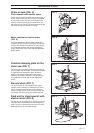
One-man sawmill with electric
motor
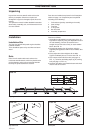
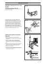
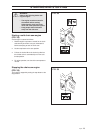
Install the bar (FIG. 29)
Install the chain and bar on the motor unit as follows:
1.Secure the chain around the motor unit’s sprocket.
Ensure that its teeth correspond with the direction of
rotation according to the arrow (A).
2.Position the bar and thread the chain around the
bar. CAUTION! Ensure that the tip of the tension
screw’s nut (B) fits into the hole on the bar.
3.Install the guide (C) and loosely tighten the two bar
bolts (just so that there is no play on the bar).
4.Adjust the chain using the tension screw. Tighten to
a torque of 30 Nm.
5.The direction of rotation is changed using the phase
inverter (D).
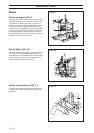
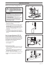
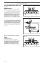
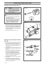
One-man sawmill with electric
motor and feed (FIG. 30)
Install the control unit and electric motor as follows.
1.Install the feed unit at the end of the rails.
2.Insert the cable with the connecting nipple through
the profile by the feed unit.
3.Route the cable around the adjuster pulley (A) at the
other end and route it back to the saw carriage.
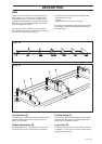
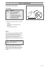
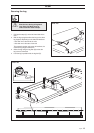
4.Wind the cable once around the wheel (FIG. 31 E)
on the feed motor.
5.Connect the cable in the connector (FIG. 31 B).
CAUTION! The spring must be facing the feed unit.
6.Connect the connector in the saw carriage (FIG. 31
C).
7.Tension the cable and lock the adjuster pulley (FIG.
31 D) so that the spring stretches approximately 5
mm.
A
B
9
A
B
C
D
C
B
E
D
A