Assembly - 13
ASSEMBLY
Grease
Use a SAE Multi-purpose grease based on the expected air
temperature range during the service interval.
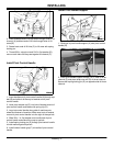
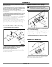
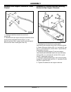
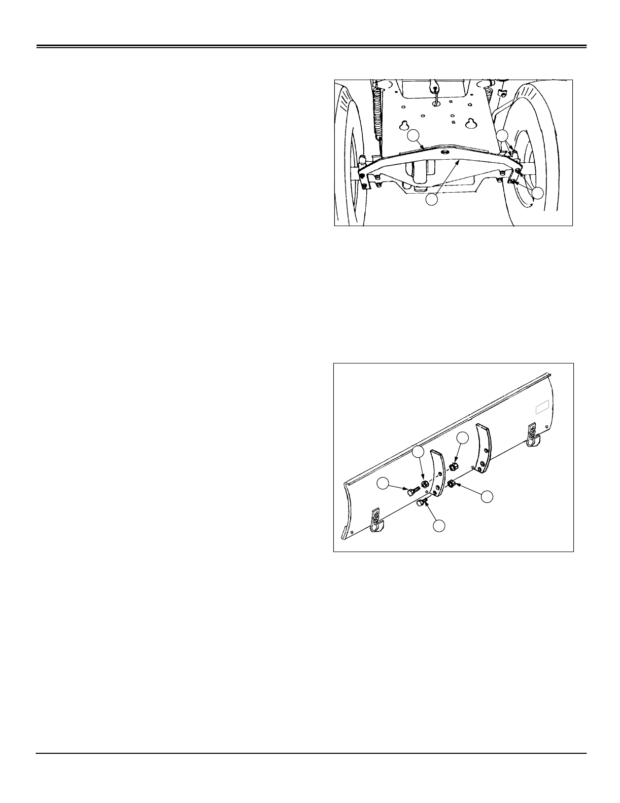
Install Drawbar Support Plate
1. Place drawbar support plate (A) under rear axle and
under drawbar (B).
2. Align drawbar holes with axle holes.
3. Install four 5/16 x 2-1/2 in. hex head bolts (C) and four 5/
16 in. lock nuts (D).
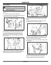
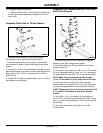
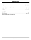
Install Parts to Blade Assembly
1. Assemble spring anchor bolts:
a. Turn one 5/16 in. nut and lock washer assembly (B)
onto the 5/16 x 1-1/4 in. hex head bolt (A) with lock
washer away from the head of the bolt.
b. Insert the bolt and nut assembly (A & B) through hole
in rib of blade assembly then assemble with a second 5/
16 in. nut and lock washer assembly (C) onto bolt (A).
c. Adjust inside nut and lock washer (B) flush with end
of thread on bolt then tighten nut and lock washer (C)
against blade rib.
d. Assemble second 5/16 x 1-1/4 in. bolt to opposite
side of blade assembly using the same procedure.
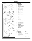
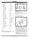
2 Flat Washer 5/16 Flat
3 Cotter Pin .094 x.75
1 Flat Washer 1/2 x 2 in.
2 Flat Washer 3/8 x 1-1/2 in.
4 Hex Head Bolt 5/16 x 1-1/4 in.
2 Hex Head Bolt 5/16 x 5/8 in.
4 Hex Head Bolt 5/16 x 2-1/2 in.
3 Flat Washer 3/8 x 1 in.
3 Lock Washer 3/8 in.
1 Nylock Nut 5/8 in.
1 Eye Bolt 3/8 x 2 in.
6 Hex Lock Nut 5/16 in.
1 Hex Head Bolt 5/8 x 1-3/4 in.
2 Hex Head Bolt 1/2 x 1in.
8 Spring Locking Pin .095 DIA x 1-5/8 in.
1 Spring Locking Pin 0.148 DIA x 2-7/8 in.
1 Flat Washer 21/32 x 1-5/16 in.
1 Hitch Pin 5/8 x 1-7/8 in.
2 Spring Clip .065 DIA x.72 in. OD
1 Full Thread Bolt 3/8 x 2-1/2 in.
2 Hex Lock Nut 1/2 in.
2 Flat Washer 1/2 x 1-1/2 x 3/16 in.
8 Nut/Lock Washer Assembly 5/16 in.
13 Hex Head Bolt 3/8 x 1 in.
18 Nylock Nut 3/8 in.
3 Hex Nut 3/8 in.
Qty Description Size
A
B
D
C
M93033B
B
A
C
D
E


