


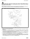
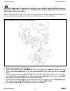
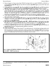

5. Install the stationary stirrer (see #20, fig. 3) using M8x45 hex bolt (see #31, fig. 3), two Ø8 flat
washers (see #38, fig. 3), and one M8 elastic stop nut (see #36, fig. 3) that are already bolted to
the stirrer.
6. Install protection (see #5, fig. 3) using two M8x20 carriage bolts (see #28, fig. 3), two Ø10 fender
washers (see #42, fig. 3), two Ø8 lock washers (see #40, fig. 3) and secure with two M8 hex nuts
(see #34, fig. 3). Install attachment plate (see #6, fig. 3) on protection using M8x16 hex bolt (see
#27, fig. 3), two Ø8 flat washers (see #38, fig. 3) and secure with M8 hex nut (see #34, fig. 3),
then install it to the hopper using M8x20 carriage bolt on model SS1036 or M8x25 on model
SS2036 (see #28, fig. 3), on model SS2036 use bolt already installed on hopper, and secure with
Ø8 flat washer (see #38, fig. 3), Ø8 lock washer (see #40, fig. 3) and a M8 hex bolt (see #34, fig.
3).
7. Install shutter assembly found in the hardware bag by sliding shutters (see #7 & #8, fig. 3) into the
slots at bottom of the hopper.
8. Assemble shutter guide plate (see #11, fig. 3) to lever bracket (see #12, fig. 3), which is already
installed on the frame using M8x30 hex bolt (see #29, fig. 3), Ø8 lock washer (see #40, fig. 3),
and M8 hex nut (see #34, fig. 3).
9. Install lever (see #16, fig. 3) to lever bracket using one M8x20 hex bolt (see #26, fig. 3) which is
shipped installed on the lever. Secure bolt with M8 hex nut (see #34, fig. 3).
10.Tighten all hardware.
11.Install driveline and ensure it has at least 2” from bottoming out in its shortest working position and
has the minimum 6” overlap in its longest working position. Refer to Section 4.03
2
of this manual,
if it is determined that the driveline is too long and needs to be shortened. Contact your local
dealer if it is determined that the driveline is too short for your tractor.
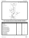
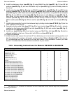
1.05 - Assembly Instructions for Models SS1067B & SS2067B
Each unit is shipped with a hardware bag that consists of the following:
33Washer flat Ø14 (5BP0091435)
1011Washer flat Ø8 (5BP0015230)
-1Washer lock Ø8 (5BP0003144)
88Washer lock Ø6 (5BP0046536)
88Nut HH M06-1.00 C6 Z TK (5BP501603B)
56Nut HH M08-1.25 C6 Z MD (5BP0046545)
66Nut HH M12-1.75 C6 Z MD (5BP0001106)
88Bolt HH M06-1.00x16 C8.8 Z F (5BP0036319)
22Bolt HH M08-1.25x20 C8.8 Z F (5BP0015012)
33Bolt HH M08-1.25x16 C8.8 Z F (5BP0046454)
-1Bolt CR M08-1.25x20 C4.6 Z (5BP0084289)
3-Bolt CR M12-1.75x40 C8.8 Z (5BP0044115)
-3Bolt CR M12-1.75x30 C4.6 Z (5BP0051073)
1-Attachment plate (5BP0014339) (#2, fig. 5)
-1Attachment plate (5BP0014338) (#2, fig. 5)
Hardware bag contains the following:
11Driveline
11Stationary stirrer (#21, fig. 4)
44Spreader wings (#20, fig. 4)
11Protection (#1, fig. 5)
11Protection (#4, fig. 4)
11Shutter assembly (#9, fig. 4)
11Scaled rod (#17, fig. 4)
11Hitch lever (#15, fig. 4)
11Lever (#14, fig. 4)
Model SS2067B Qty.Model SS1067B Qty.Description
FERTILIZER SPREADERS OPERATOR’S MANUAL
GENERAL INFORMATION 8 FRONTIER
2
See Section 4.03 - Driveline, for instructions on how to determine correct driveline length and procedures for
shortening the driveline.