


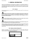

CAUTION: Stand clear of bands when cutting as they could be under sufficient tension to
cause them to fly loose. Take care in removing bands and wire. They often have extremely
sharp edges and cut very easily.
NOTE: Assembly will be easier if all parts are loosely assembled before tightening the hardware. All
hardware needed for assembly will be found in the hardware bag or on the machine.
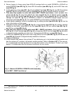
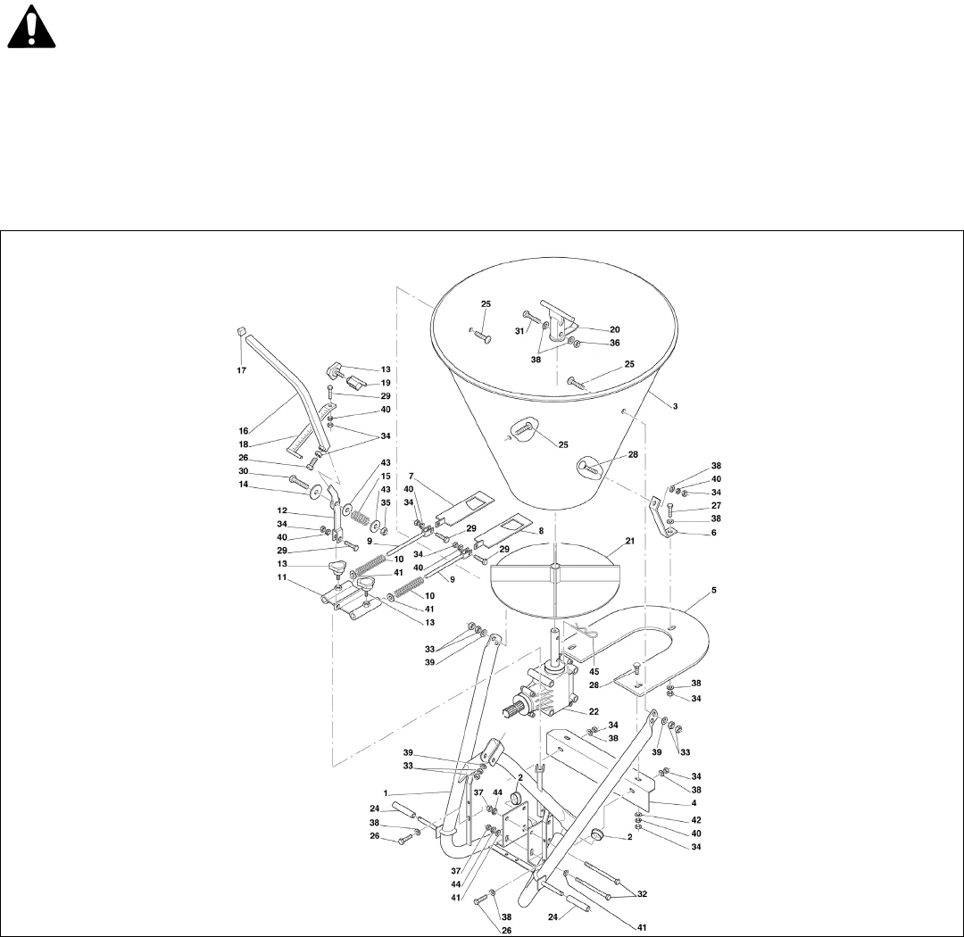
To assemble the spreader do the following:
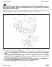
1. Attach spreader disc (see #21, fig. 3) to the output shaft of the gearbox using hairpin cotter (see
#45, fig. 3).
2. Locate scaled rod assembly (see #18, fig. 3) in hardware bag. Install scaled rod to main frame
using M8x30 bolt (see #29, fig. 3), Ø8 lock washer (see #40, fig. 3), M8 hex nut (see #34, fig. 3)
that are already installed on the scaled rod assembly.
3. Install protection (see #4, fig. 3) onto spreader frame using two M8x20 hex bolts (see #26, fig. 3),
four Ø8 flat washers (see #38, fig. 3), and two M8 hex nuts (see #34, fig. 3).
4. Slide hopper onto the output shaft of the gearbox. Secure hopper to frame using three M8x25
carriage bolts on model SS1036 or M8x35 on model SS2036 (see #25, fig. 3), three Ø8 fender
washers (see #39, fig. 3), and six M8 hex nuts (see #33, fig. 3).
FERTILIZER SPREADERS OPERATOR’S MANUAL
GENERAL INFORMATION 7 FRONTIER
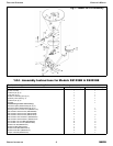
Fig. 3 - Model SS1036B & SS2036B assembly.