


ASSEMBLY
OM 0391SB1274-A
16
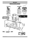
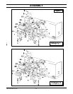
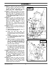
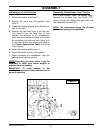
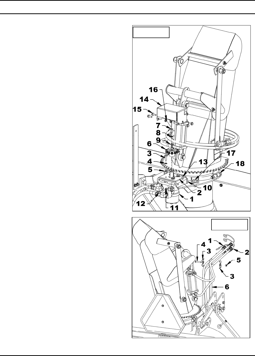
11. Figure 7: Install the motor (item 1) placing
the anchor plate on top (item 2) as shown
on figure. Attach with four 3/8"NC x 1 1/4"
(item 3) hex. bolts, lockwashers and flat
washers (items 4-5). Tighten manually.
12. Figure 7: Grease the inside of the motor
gear (item 6) and install with the key, 8mm x
20mm bolt (item 7), lockwasher and flat
washer (items 8-9). Tighten according to the
"Torque Specification Table" at the end of
the manual.
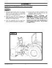
13. Figure 7: Insert the anchoring flat bar
(item 10) between the anchor plate (item 2)
and the motor support as shown on figure.
Screw the 3/8"NC nuts (item 11) at
maximum on the two 3/8"NC x 1 1/2" lg
bolts (item 12). Install those two bolts
(item 12) by screwing them in the anchoring
flat bar (item 10).
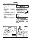
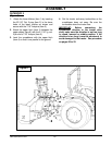
14. Figure 7: Adjust the distance between the
chute gear and the motor gear according to
the following step:
A. Slightly unscrew the two bolts (item 17)
that hold the retaining plate.
B. Screw the two nuts (item 18)
simultaneously until the distance between
the retaining plates and the chute base is
leveled.
C. Retighten the bolts (item 17) according to
the "Torque Specification Table". at the
end of the manual.
D. Adjust the gears to a distance between
1/32" and 1/16" by screwing the two bolts
(item 12). Secure with the nuts (item 11)
moving them against the anchoring flat
bar (item 10). Tighten the four bolts
(item 3) at 30 lbs-ft (41 N-M).
E. Run a test at low speed. If the gears have
an irregular sound while testing, it means
the adjustment is incorrect. Bring parts
closer to each other until the sound
becomes regular and even.
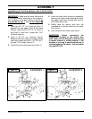
15. Figure 7: Reinstall the gear and the cover
(item 13) with four 5/16" x 1" bolts (item 14),
3/8" flat washers (item 15) on the outside
and 5/16" serrated flange nuts (item 16) on
the inside. Tighten according to the
"Torque Specification Table" at the end of
the manual.
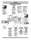
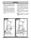
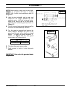
16. Figure 8: Attach the motor and cylinder
hoses (items 1-2) on each side of the hose
support (item 6) with two hose clamps
(item 3), a 3/8"NC x 2" hex. bolt (item 4) and
a 3/8"NC nylon insert nut (item 5).
Figure 7
Figure 8