


ASSEMBLY
OM 0391SB1274-A 12
S
NOWBLOWER ASSEMBLY
The snowblower is assembled at the factory; however, certain components must be assembled. Use the
present manual and lay out all parts for assembly. Separate bolts and nuts into various sizes. After
assembly, torque all the bolts according to the Torque Specification Table enclosed at the end of the
manual.
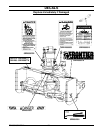
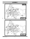
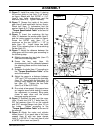
Installation of the Three Point Hitch
(Figures 1-2)
NOTE: Pay particular attention to the position of
the lower hitches. The overhang of the bent
section must be on the outside for Cat. 1
and
on the inside for Cat. 2
as illustrated.
1. Remove the knob (item 8) and the rear guard
(item 9).
2. Attach the lower hitches (items 1-2) to the
snowblower with two 3/4"NC x 5" hex. bolts
(item 7), 3/4" lockwashers and 3/4" nylon
insert nuts (items 5-6). Place the two
reinforcement plates (item 3) under the lower
hitches and secure with four 3/4"NC x 5" bolts
(item 4), two 3/4"NC x 5 1/2" bolts (item 3),
3/4" lockwashers and 3/4" nylon insert locknuts
(items 5-6).
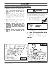
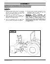
3. Attach the hitches (items 10-11) to the lower
hitches (items 1-2) as illustrated with two
3/4"NC x 2" bolts (item 12) and 3/4" Stover
nuts (item 13).
4. Fasten each hitch (items 10-11) to the upper
hitch (item 14) with a 3/4"NC x 5 1/2" bolt and
a 3/4" Stover nut (item 13). Attach the upper
hitch (item 14) to the snowblower with a
3/4"NC x 4" bolt (item 16) and a 3/4" Stover
nut (item 13).
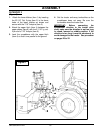
5. Attach the hose support (item 17) to the upper
hitch (item 10) in the position shown with two
3/8" NC x 1 1/4" serrated flange bolts and two
3/8" serrated flange nuts (items 24-25).
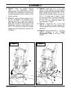
6. Reinstall the rear guard (item 9) with the knob
(item 8).
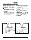
7. Install the eyebolt (item 20) in the upper hole of
the left or right side of the three point hitch by
screwing the eyebolt nut to the top and locking
eyebolt in place with a 3/8" serrated flange nut
(item 21).
8. Tighten all bolts according to the "Torque
Specification Table" at the end of the
manual.