ASSEMBLY
OM 0391SB1274-A
14
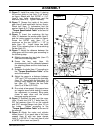
1. Hydraulic hose
2. Cardboard
3. Ma
g
nif
y
in
g
g
lass
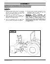
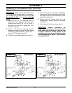
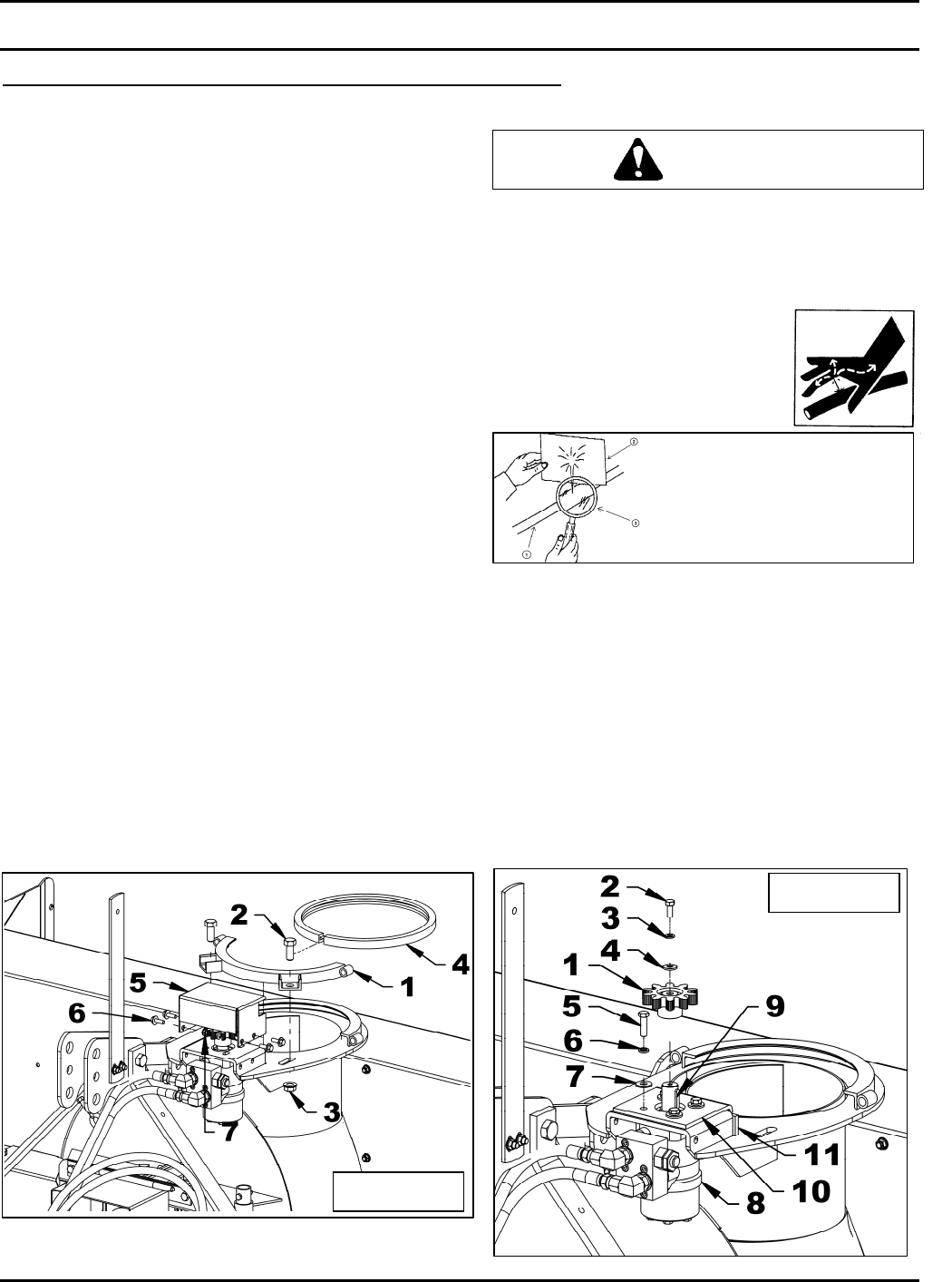
Installation of the Chute and the Hydraulic Rotation
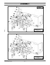
(Figures 3-4-5-6-7-8)
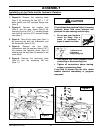
1. Figures 3: Remove the retaining plate
(item 1) by removing the two 5/8" x 1 1/2
bolts (item2) and 5/8" serrated flange nuts
(item 3).
2. Figures 3: Remove the rotation ring
(item 4) and the gear shield (item 5) by
removing the four 5/16" x 1" serrated flange
nuts (item 6) and the 5/16" serrated flange
nuts (item 7).
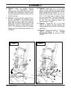
3. Figure 4: Take off the motor gear (item 1)
by removing the bolt, the lockwasher and
the flat washer (items 2-3-4).
4. Figure 4: Remove the four bolts,
lockwashers and flat washers (items 5-6-7)
the remover the hydraulic motor (item 8)
making sure the key (item 9) remains in the
motor shaft.
5. Figure 4: Remove the anchoring plate
(item 10) and the anchoring flat bar
(item 11).
To avoid serious personal injury. Escaping
hydraulic/ diesel fluid under pressure can
penetrate the skin causing serious injury
.
• Do not use your hands to
check for leaks. Use a
piece of cardboard or
paper to search for leaks.
• Stop engine and relieve pressure before
connecting or disconnecting lines.
• Tighten all connections before starting
engine or pressurizing lines.
If any fluid is injected into the skin, obtain
medical attention immediately or gangrene
may result
CAUTION
Figure 4
Figure 3


