


28 Dealer Service
5WPMAN0183 (Rev. 4/25/2008)
NOTICE
Improper positioning of seals can cause seal
damage. An improperly installed seal will leak and
could cause bearing failure.
5. Apply a thin coat of Permatex to the area of hous-
ing where seals seat.
6. Install bottom seal with spring up toward center of
housing.
7. Place seal squarely on housing and select a piece
of pipe or tubing with an OD that will set on outside
edge of seal. A tubing with an OD that is too small
will bow seal cage.
8. Carefully press seal into housing to prevent distor-
tion to metal seal cage. Bottom seal should seat
firmly and squarely against machined shoulder in
housing.
9. Make sure seal lip did not roll under. Distortion to
seal cage or damage to seal lip will cause seal to
leak. Damaged seals must be replaced.
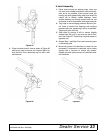
10. Insert shaft and bearing through bottom of housing.
11. Fill housing cavity with a medium grade grease.
12. Install top bearing on shaft to mate with top cone.
13. Apply a thin coat of Permatex to shaft area where
sleeve will seat.
14. Install sleeve on shaft and press sleeve and bear-
ing into housing until all free play is removed and
there is a very light drag on bearings (similar to
adjusting front wheel bearings on an automobile).
Check by spinning spindle. It should turn freely.
15. Be careful not to overtighten bearings. Proper
bearing adjustment is essential to good bearing
life.
16. If you overtighten bearings, hold spindle housing
and rap spindle shaft with a lead hammer.
17. Carefully press top seal in with spring up. Top seal
should be flush with or to within 1/16" (2 mm)
above the housing.
18. Rotate housing on spindle shaft, checking for free
movement.
19. Install grease fitting in spindle shaft.
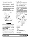
Spindle Installation
NOTICE
Pulley installation sequence is very important
for bearing life. Follow the sequence exactly.
1. Install spindle through bottom of mower and secure
with four mounting bolts.
2. Install pulley and split taper bushing with integral
key on spindle shaft. Make sure bushing is in con-
tact with sleeve on spindle shaft.
3. Alternately tighten split taper bushing cap screws
to 12 lbs/ft. (16 N-m).
4. Install toothed lock washer and nut on spindle
shaft. Tighten nut until snug. Bend up edge of lock
washer against a flat side on nut.
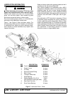
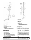
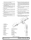
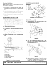
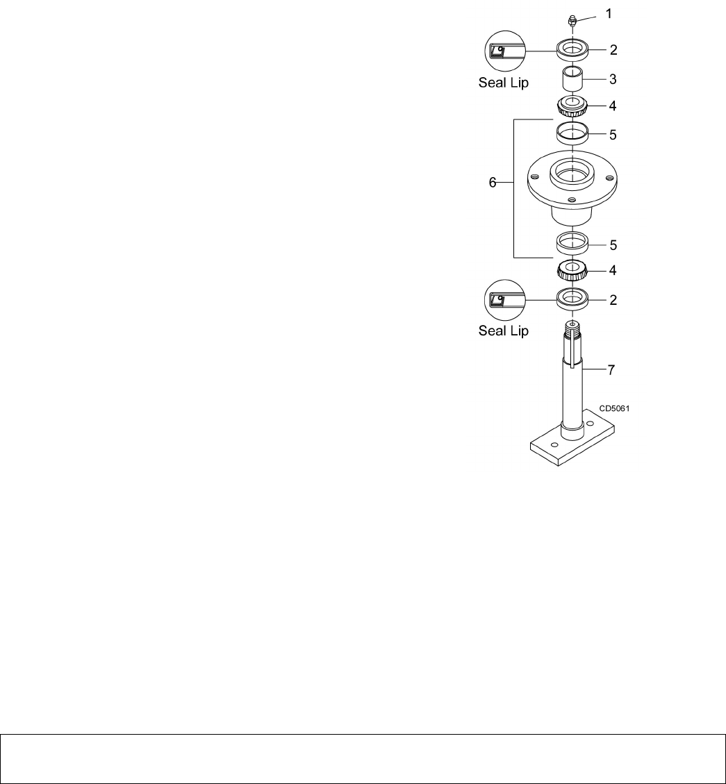
1. Grease fitting
2. Seal, 1.50 x 2.12 x .31
3. Sleeve, 1.14 x 1.50 x .55
4. Bearing cone
5. Bearing cup
6. Spindle, Housing
7. Shaft, Blade spindle
Figure 17. Spindle and Shaft Assembly