


14 Operation
5WPMAN0183 (Rev. 4/25/2008)
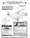
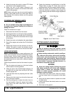
4. Attach the mower drive shaft to tractor PTO. Make
sure the lock collar engages securely.
5. Attach the end of the mower transport's lock
release rope to a location on the tractor within easy
reach of the operator.
NOTE: When routing the rope, do not route through the
hydraulic hose guide and do not allow rope slack to
drop between the driveline shields and the gearbox
rotating shafts.
CV DRIVELINE TURNING LIMITS
NOTICE
Do not exceed turning angle of 80 degrees at
the head of the Constant Velocity (CV) driveline or
damage will occur.
Check for excessive turn angle:
1. Disconnect the driveline from the tractor.
2. Start engine and turn as far right or left as possible.
3. Shut off the engine and connect the CV driveline to
the tractor. If it cannot be connected, the turn angle
is too severe.
4. Restart the tractor and straighten the angle slightly.
5. Shut off the engine and connect the CV driveline to
tractor.
6. Repeat the process until the driveline can be con-
nected. The point at which the driveline can be
connected is the maximum turn that can be made.
LEVELING MOWER
NOTE: To ensure satisfactory mower performance, the
trailer frame and decks must be leveled before operat-
ing the mower. During normal operation the mower
should be leveled twice each season. The mower must
be leveled each time a tractor with a different drawbar
height is used.
Follow this procedure to level the flex mower for opera-
tion:
1. Park the tractor and mower on a flat level surface
with the decks in mowing position.
2. Inflate all tires to the recommended pressure: 70
psi (483 kPa) for trailer tires and 30 psi (207 kPa)
for deck gauge tires.
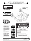
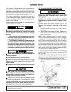
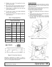
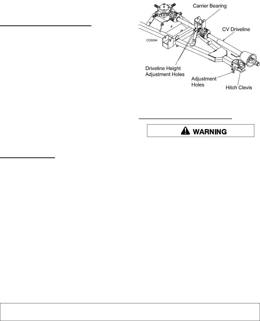
3. Level the trailer frame by adjusting the hitch. (See
Figure 2.)
4. Remove the hitch clevis from the trailer frame and
pin to the tractor drawbar.
5. Use the parking jack to adjust the trailer frame to
the level position. Align the nearest hitch adjust-
ment hole in the hitch clevis with a hole in the
trailer frame.
6. Tighten the hardware to specifications in the Bolt
Torque Chart on page 57. Frame level must be
readjusted each time the drawbar height changes.
7. Attach the mower and the driveline to the tractor.
Level the driveline by placing a bolt through the
carrier bearing and the driveline height adjustment
holes.
Figure 2. Level Trailer Frame
CUTTING HEIGHT ADJUSTMENT
Keep all persons away from operator control
area while performing adjustments, service, or
maintenance.
Before working underneath, carefully read Oper-
ator’s Manual instructions, disconnect driveline,
raise mower, securely block up all corners with
jackstands, and check stability. Secure blocking
prevents equipment from dropping due to hydrau-
lic leak down, hydraulic system failures, or
mechanical component failures.
NOTICE
Avoid low cutting heights. Striking the ground
with blades produces one of the most damaging
shock loads a mower can encounter. Allowing
blades to contact ground repeatedly will cause
damage to mower and drive.
1. Level mower from side to side. Check by measur-
ing from mower frame to the ground at each deck
rail.
2. Verify that the same amount of spacers are under
all caster arms.
3. Loosen cap screws that attach caster arm assem-
bly to deck.
4. Set mower on the ground.