


26 Dealer Service
5WPMAN0183 (Rev. 4/25/2008)
DEALER SERVICE
The information in this section is written for dealer ser-
vice personnel. The repair described here requires
special skills and tools. If your shop is not properly
equipped or your mechanics are not properly trained in
this type of repair, you may be time and money ahead
to replace complete assemblies.
Before working underneath, read manual
instructions, securely block up, and check stability.
Secure blocking prevents equipment from drop-
ping due to hydraulic leak down, hydraulic system
failure, or mechanical component failure.
Keep all persons away from operator control
area while performing adjustments, service, or
maintenance.
Always wear relatively tight and belted clothing
to avoid entanglement in moving parts. Wear
sturdy, rough-soled work shoes and protective
equipment for eyes, hair, hands, hearing, and head;
and respirator or filter mask where appropriate.
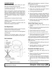
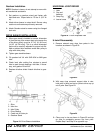
BLOCKING METHOD
Do not work underneath mower unless it is properly
attached to the tractor and blocked securely. When
properly attached, the unit will be anchored to minimize
front to rear movement.
The only approved blocking device for this mower is a
jackstand with a load rating of 1000 pounds (454 kg) or
more. One jackstand under each corner of each deck
(12 total) must be installed before working underneath
this unit.
Before blocking, be sure that the mower is securely
attached to the tractor. Lower mower units to the
ground. Raise the mower units as needed for working
room and securely block them. Set tractor brakes, turn
engine off and remove key, then disconnect mower
driveline.
When blocking, you must consider the overall stability
of the unit. Just placing jackstands under the unit will
not ensure your safety. The working surface must be
level and solid to support the loaded weight of the jack-
stands. Ensure that jackstands are stable at both top
and bottom. Before working under any portion of the
mower, test the stability of your blocking with the full
weight of the mower units lowered onto the jackstands.
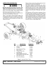
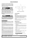
Figure 14. Jackstand Placement
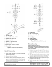
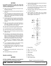
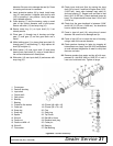
BLADE SPINDLE
Servicing
Spindle repair requires special skills and tools. If your
shop is not properly equipped or your mechanics are
not trained in this type of repair, you may be time and
money ahead to use a new spindle assembly.
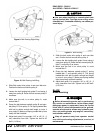
For reference, the grease fitting is in the top of the spin-
dle shaft.
Permatex
®1
3D Aviation Form-A-Gasket or equivalent
is recommended as a sealant.
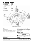
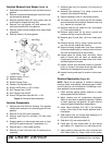
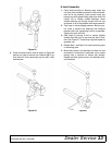
Spindle Removal
1. Remove blade from spindle.
2. Remove belt from pulleys.
3. Remove jam nut (1) and washer (3) from top of
spindle shaft.
4. Disassemble split taper bushing (5) (located on top
of pulley) by removing the two bolts (2) and wash-
ers (4).
5. Insert bolts (2) into the threaded holes of bushing
flange.
6. Tighten bolts alternately to remove split taper bush-
ing.
7. Remove pulley (6).
8. Remove bolts (19) that attach spindle to mower
frame and remove spindle.
9. Remove grease fitting (21) from top of shaft.
CAUTION
1. Permatex is a registered trademark of the Permatex
Corporation.