


Dealer Service 27
5WPMAN0183 (Rev. 4/25/2008)
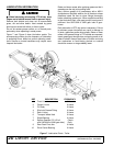
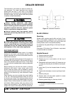
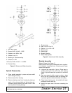
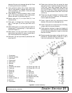
1. Nut, Jam 7/8 NF
2. Screw, HHCS 1/4 NC x 1 GR5
3. Washer, Lock .929 x 1.66
4. Washer, Lock 1/4
5. Bushing, H 1 Strt bore w/key
6. Sheave, H 1 BK
19. Screw, HHCS 1/2 NF x 1-1/4 GR5
21. Grease fitting
Figure 15. Sheave and Blade Assembly
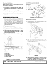
Spindle Disassembly
1. Place spindle assembly in press and press shaft
down through housing.
2. Remove seals from housing.
3. Remove bearing cups from housing by placing a
punch in the slots provided and driving them out.
Alternate punch positions from side to side. Take
care to prevent housing damage.
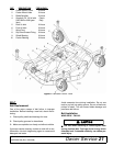
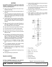
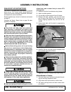
1. Grease fitting
2. Seal, 1.50 x 2.12 x .31
3. Sleeve, 1.14 x 1.50 x .55
4. Bearing cone
5. Bearing cup
6. Spindle, Housing
7. Shaft, Blade spindle
Figure 16. Spindle and Shaft Assembly
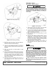
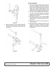
Spindle Assembly
Refer to Figure 16 or Figure 17.
Bearing cones and cups are designed to work together.
It is important to position them so bearing cone taper
mates with cup taper.
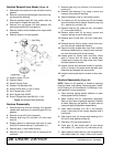
1. Lubricate new cups with a light oil. Place them in
spindle housing so they will mate with bearing
cones. Cups and cones are a press fit to minimize
wear.
2. Seat cups securely with a press or place a large
drift in the flat lip and drive them into housing until
cup seats against machined shoulder of housing.
3. Place bottom bearing cone into spindle with taper
positioned to mate with cup.
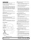
4. Identify the open side of the seal containing the
spring.