


Diagnostic LEDs
DK01672,000010A -19-15JUL11-1/1
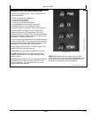
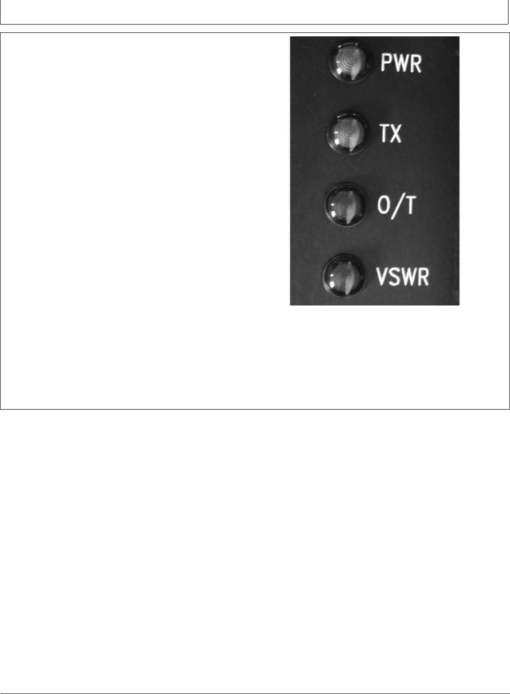
Amplier LEDs (USA and Canada only)
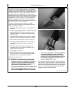
There are four amplier LEDs. They are located on the
side of the amplier.
The LEDs can be used to determine
□ Is the amplier powered?
□ Is there an internal failure?
□ Is the radio signal being amplied?
□ Is the amplier setup causing it to overheat?
□ Is the antenna or its connection path faulty?
The LEDs operate in two states: Start Up and Operation.
After the amplier is initially powered, the amplier
strobes through each LED sequentially. This rapid
ashing sequence indicates that the internal rmware test
sequence is initiated. It checks the power to the unit and
the integrity of internal components.
The outcome of a successful startup test sequence results
in only the PWR LED on. The outcome of an unsuccessful
startup sequence results in the PWR LED and any of the
red LEDs on. These red LEDs indicate a failure.
During normal operation after a successful startup, each
amplier LED has a specic meaning.
Power LED Indicates that the amplier has DC power.
TX LED Indicates that an RF signal is being actively
amplied and transmitted. This light blinking indicates
normal function.
O/T LED Indicates that the unit has exceeded its internal
temperature limits. When this light is on, the unit will
cease amplication. This allows the unit to cool and
prevents permanent damage.
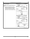
PUPC000031 —UN—07DEC09
Amplier LED
VSWR LED Indicates that the antenna path is faulty.
When this light is on, the unit will cease amplication. This
prevents the output power from being reected back into
the amplier and causing permanent damage.
35-2
092711
PN=27