


RTK Base Station Setup
DK01672,0000145 -19-25JUL11-2/2
Continued onnext page DK01672,0000139 -19-22JUL11-1/2
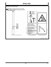
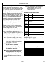
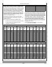
John Deere RTK Radio 450 High Gain Antenna
Model Number PF81452
Gain
7 dBi
Frequency Range 435-470 MHz
Max Power
200 W (UHF)
Impedance
50 OHMS
VSWR
< 1.7:1
RF Connector
N-FEMALE
Length
81 in (2 m).
Fiberglass Tube dia
2 in (5 cm)
Base Pipe
11 in (28 cm) long, 2 3/8 in (6 cm)
dia
Wind Survival 100 MPH (161 km/h)
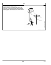
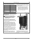
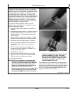
Always mount the radio antenna vertically to make sure
that the RTK signal is radiating outwards. If the antenna is
at an angle, it may cause the data received at the vehicle
to be lower than expected.
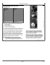
NOTE: The RTK Radio 450 whip antenna, PF81464
(450-470 MHz) and PFP10612 (435-450 MHz),
looks similar to 900 MHz and 869 MHz RTK
whip antennas. To differentiate, it has a white or
green stripe near its tip. The white stripe labels
the 450 - 470 MHz antenna and the green stripe
labels the 435 - 450 MHz antenna.
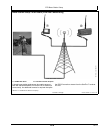
Base Station Setup—Amplier Option (USA
and Canada only)
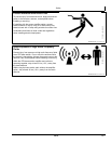
CAUTION: Install and operate the amplier
safely. Read and follow PREVENT ELECTRICAL
SHOCK AND FIRES and AVOID EXPOSURE
TO HIGH RADIO FREQUENCY FIELDS in
the SAFETY section.
The primary reason for RTK Radio 450 is to provide
a more robust RTK data link. Signal strength is the
dominant factor in the link reliability and range. For areas
where there are trees and other foliage, John Deere offers
an optional in-line amplier.
The PF81443 amplier is a UHF RF power amplier
intended for use in RTK Radio 450 system. It is not
intended to be used with standard (869MHz, 900MHz)
RTK or any other applications. The amplier can deliver
RF power from 0 to 50 W proportional to the 0 to 2 W input
from RTK Radio 450. It covers a frequency range from
450 MHz to 470 MHz. This higher signal strength provides
greater range from the base and increased coverage in
areas with dense foliage and trees.
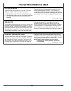
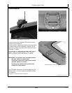
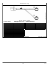
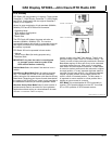
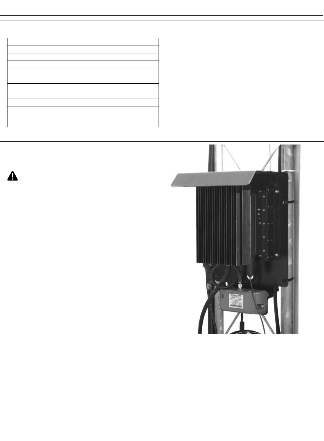
This amplier is inserted between the radio and the base
antenna. The amplier has been designed to function
outdoors attached to its mounting plate with sun shade.
Mount the amplier in an area where air can freely
circulate around it. If possible, mount in a location shaded
from direct sunlight.
Operation of the amplier inside an enclosure is not
recommended. Poor ventilation within the box can
cause the amplier to overheat. While this would not
PUPC000027 —UN—06DEC09
Amplier Assembly
permanently damage the amplier, it would cause it to
stop amplication. The output signal would no longer be
strong enough for the vehicles in the eld to receive.
25-4
092711
PN=15