SERVICE
Description of SteamPro Steam Generator
The SteamPro series generator is the latest in modern steam generator design. The SteamPro steam generator uses a
printed circuit assembly to monitor and control all the equipment needed to produce steam. The system has three functions:
a timer that controls the length of the steam bath; the operating water level is monitored and controlled; and the heating
elements are protected by a minimum water level sensor. The generator is compartmentalized into wiring, control and
tank sections. The elements can be removed through an access opening on the service side.
Maintenance of SteamPro Generators
Maintenance of the SteamPro generator includes flushing the unit periodically and visually inspecting for water leaks.
Whenever the generator is opened all wiring should be inspected for any signs of overheating. All electrical connections
should be checked for tightness.
Repair of SteamPro Generators
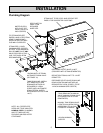
A. ELEMENT REPLACEMENT: Disconnect power from the unit. Drain the tank. Open the front and HEATING
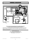
ELEMENT ACCESS covers. Note the wire connections. See diagram. Remove the element wires. Using a hot
water element socket, remove the element. To install a new element, mount a new element gasket on the element.
Clean the element port and add a light coat of Rectorseal No. 5 pipe thread compound to the threads. Insert and
hand tighten the element-gasket combination. Notice the element end orientation as shown in diagram. Tighten
the element until the orientation is the same as diagram, ± 15°. The gasket should be set and tight but not
deformed to a rounded or bulbous appearance. If the drain valve was removed reinstall it. Reconnect the wiring.
Test the unit. Check for leaks at the element. Replace the front cover and the HEATING ELEMENT ACCESS
cover.
B. PRINTED CIRCUIT REPLACEMENT: Disconnect power from the unit. Remove the front cover. Note where the
blue wire is connected to the triple pronged water level probe. Disconnect all three wires from the water level
probe. A u-clip on the shelf is retaining these three wires. Slightly bend this u-clip to free the three wires. Discon-
nect the two blue wires from the water solenoid and (3) wires connected to TB1. Note and tag the position of all
wires that plug into the printed circuit assembly mounted relays. Remove all the wires from the relays. When
removing these wires pull on the connector and not the wire. Five screws hold the board in place. Remove all five
screws. The printed circuit assembly can now be removed. To install the board reverse this procedure. Test the
unit.
IMPORTANT
The blue wire connected to "L" and "P3" on the PCA must be connected
to the shortest of the three level probes.
C. WATER SOLENOID REPLACEMENT: Disconnect power from the unit. Turn the water supply OFF. Disconnect
the water supply from the water solenoid valve. Remove the front cover. Remove the two blue wires from the water
solenoid valve. Rotate the self-tightening hose clamp so it can be loosened with a pair of pliers. Squeeze the
clamp and move it down towards the shelf and off the valve outlet tube. Remove the two 1/4" - 20 hex head bolts
and lock washers that attach the valve to the chassis. Pull the valve off the rubber fill hose. To install the valve,
reverse these instructions. Test the unit.
D. LEVEL PROBE REPLACEMENT: Disconnect power from the unit. Remove the front cover. Note where the blue
wire is connected to the triple pronged water level probe. Disconnect all three (3) wires from the water level probe.
Using a 1-1/4" box wrench, remove the level probe. Install a new level probe. Tighten until the bottom of the plastic
nut is 1/8" to 3/8" inch above the top of the port. Reattach the three (3) wires. Test the unit.
IMPORTANT
The blue wire connected to “L” and “P3” on the PCA must be connected
to the shortest of the three level probes.
IMPORTANT
The level probe may be extremely tight. Damage to the insulation or chassis may result unless
the tank is properly blocked or supported during probe removal or installation. It may be neces-
sary to completely disconnect and disassemble the generator.
15


