INSTALLATION
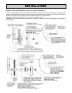
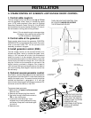
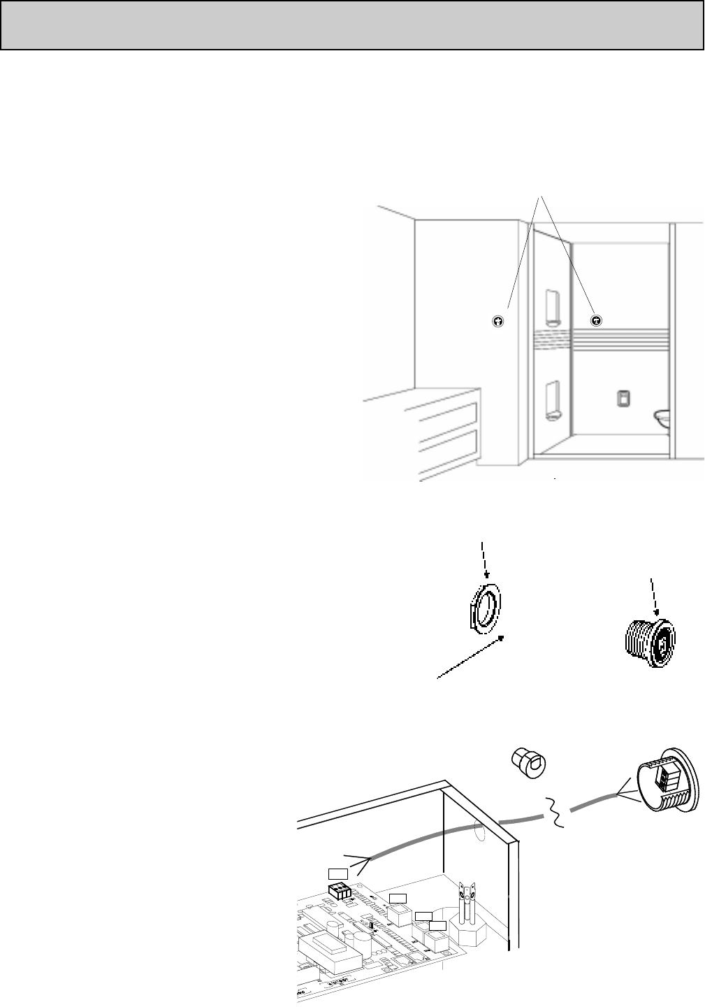
APPLY SEALANT
(100% SILICONE CAULK)
1-3/4" DIAMETER HOLE
IN FINISHED WALL
(OPTIONAL NUT INSTALLATION
IF BACK OF WALL IS
ACCESSABLE)
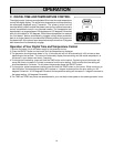
A. STEAM CONTROL BY 30 MINUTE LOW VOLTAGE ON/OFF CONTROL.
THIS LOW VOLTAGE CONTROL CAN
BE LOCATED INSIDE OR OUTSIDE
THE STEAM ENCLOSURE
1. Control cable rough-in:
The low voltage control can be mounted up to 75 feet
from the generator either inside or outside the steam
room. (A 25’ cable provided.) Also, see # 4 Optional
Secondary Generator Control. String (3) 18 to 22 AWG
solid wires from the control location through 1/2" holes in
the wall studes or ceiling joists to the generator.
Note: 1) Do not staple through or damage wires,
2) Label or color code wires for proper TB1
to R30i orientation. See diagram.
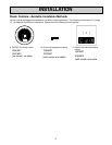
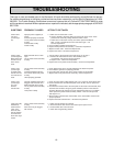
2. Control cable at the generator
Route control wires through the generator CONTROL
WIRING ENTRY and appropriate strain relief. Connect 3
wires to terminal block TB-1 on the printed circuit
assembly, as shown in diagram.
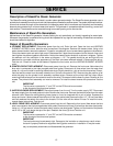
3. Install generator control (R30i)
The low voltage control can be mounted directly to a
finished wall either inside or outside the steam room.
Using a 1-3/4" hole saw, drill a hole in the finished wall
where the control is to be mounted (the control wires
should already be roughed-in to this location). Locate the
control wires, pull them out through the 1-3/4" hole and
plug the 3 wires into the connector on the back of the
control housing, as shown in diagram. Run a bead of
100% silicone caulk around the perimeter on the back of
the control housing. See diagram. Insert the control into
the wall cavity.
4. Optional second generator control
As an option, a second R30i control can be installed with
the generator to provide ON/OFF control both inside and
outside the steam room. The second control should be
installed as described in paragraphs 1 & 3, with the
second control wire plugged into the same connector TB1
connector as the first control on the PCA.
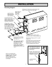
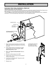
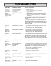
To prepare steam generator:
1. Make certain that power is disconnected.
Remove cover.
2. Remove and discard plug from hole A.
3. Feed wire through hole A and connect to
TB1 on the circuit board.
4. Locate strain relief bushing 1" from
stripped end of cable jacket with the two
connectors. Snap strain relief bushing B
into hole A.
5. Replace cover.
SK1
SK4
SK3
TB1
(3) GREEN
(2) RED
(1) WHITE
GREEN (3)
RED (2)
WHITE (1)
LOW VOLTAGE CONTROL
WIRE (25') IS PROVIDED
FOR 5 VOLT DC SWITCH
CONNECTION TO STEAM
GENERATOR. NO
ADDITONAL ELECTRICAL
SUPPLY OR WIRING
REQUIRED.
BUSHING B
HOLE A
10


