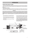
CONTROLS
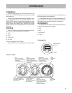
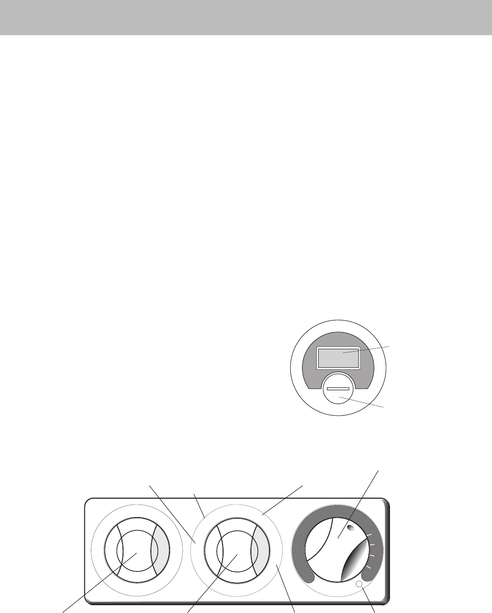
A switch panel giving you convenient control of the
JETS, filter, HTR/FLTR, lights and air blower is located
on the spa rim.
To ensure your safety and allow easy operation, your
spa is equipped with two air-activated switches. One,
the SYSTEM switch, controls the whirlpool jets, heat,
and filtration. The other switch, ACCESSORY controls
the air blower and optional light. Refer to the Control
Panel illustration for an explanation of the various switch
functions.
SYSTEM
The SYSTEM switch controls the following four func-
tions in the continuous sequence indicated:
1. OFF
2. JETS
3. HTR/FLTR
4. FILTER
(The next selection is OFF again.)
Use the JETS function as a reference to indicate your
CONTROL PANEL
8
location in the function sequence, since that function is
the most obvious when operating.
For best performance and increased equipment life,
pause a second or two between push-button selections.
Not pausing may cause the switch to malfunction.
ACCESSORY
The ACCESSORY switch controls these functions in
the continuous sequence indicated:
1. OFF
2. AIR
3. AIR/LIGHT
4. LIGHT
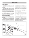
THERMOMETER
OPERATION
BATTERY
TEMPERATURE
READOUT
A
C
C
E
S
S
O
R
Y
H
E
A
T
E
R
O
F
L
I
G
H
O
F
S
Y
S
T
E
M
J
E
T
H
T
R
/
F
L
T
F
I
L
T
E
R
A
I
R
/
L
I
G
H
T
A
I
R
OFF
(Time clock controls
filter pump. Heater will turn
on with filter
pump if thermostat is set.)
JETS
(Maximum whirlpool
action. Heater will
maintain temperature set
by thermostat if converted
to 230 VAC.)
HTR/FILTER
(Filter pump and heater
will turn on as necessary
to maintain water
temperature setting.)
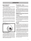
TEMP.
CONTROL
KNOB
ACCESSORY SWITCH
(Controls Air Blower and
light functions.)
SYSTEM SWITCH
(Controls Jets,
Heater/Filter and Fliter
Only functions.)
FILTER
(Filter pump will run
continuously; heater will
turn on as necessary to
maintain water
temperature setting.)
HEATER
INDICATOR
LIGHT


