17
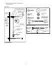
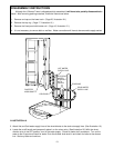
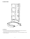
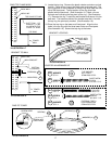
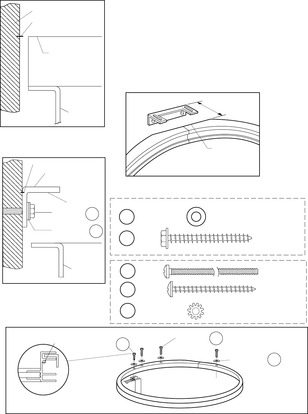
9. Locate the top ring. Remove the plastic retainer extrusion and set
it aside. Place the top ring on the fixed panel and tower wall. The
top ring groove on the underside of the top ring must mate with the
top of the fixed panel. The flat portion of the ring should be
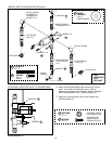
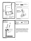
parallel with the back wall. (See Illustration 16.) Mark a line on
the back wall indicating the top plane of the ring. (See Illustration
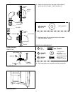
17.) Remove the ring. Locate the wall bracket and secure it to the
back wall. The bottom surface of the bracket must be in line with
the top ring line previously marked. (See Illustration 18.)
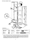
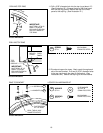
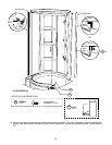
10.Place the top ring on the tower and fixed panel. Align the four
holes in the top ring with the three tower holes and fixed panel.
(See Illustration 19.) Secure the top ring to the tower.
SCREW HERE
ILLUSTRATION 17
TOWER
WALL
BOTTOM OF
BRACKET TO BE
IN LINE WITH TOP
PLANE OF RING
TOP PLANE OF RING
MARK LINE
TOP RING
ILLUSTRATION 18
TOWER
WALL
WALL BRACKET
WASHERS(2)
H11
SCREWS(2)
H12
ILLUSTRATION 19
WASHERS (4)
SCREWS (3)
SCREW INTO
FIXED PANEL
H15
H13
SCREW(1)
EXTERNAL TOOTH
LOCK-WASHER #8
STAINLESS STEEL
WASHER
QTY.-4
PAN HEAD
PHILLIPS
#8-32 x 3"
SCREW
QTY.-3
SHEET METAL
SCREW
#8-18X 2" S.S.
SCREW
QTY.-1
RING TOP PLANE MARK
BRACKET TO WALL
RING TO TOWER
MARK LINE
BOTTOM
SURFACE
BACK WALL
H13
H14
H15
H14
FLAT WASHER
#10 TYPE A
STAINLESS STEEL
WASHER
QTY.-2
H11
SHEET METAL
SCREW
#10-16X 2" S.S.
SCREW
QTY.-2
H12
ILLUSTRATION 16
FLAT PORTION
OF TOP RING
PARALLEL WITH
BACK WALL
BRACKET LOCATING
LOCATED IN HARDWARE KIT


