Page 56
J-400 Series
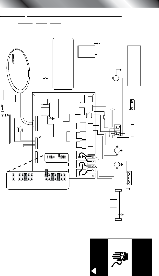
18.0 Export 50 Hz J-460/J-465/J-470/J-480
Wiring Diagram
K13
J8 J6 J7
12VAC Output Power to Lighting
Controller.
Transformer
T1
K1 K2 K3 K4 K5 K6
J4
J3
K7 K8
Options Sensors
LCD Panel
Flow
Switch
Hi-Limit/Freeze
Sensor
Temperature
Sensor
LED
Lighting
Controller
This device complies with Part 15 of the FCC rules.
Operation is subject to the following two conditions:
(1) This device may not cause harmful interference.
(2) This device must accept any interference
received including interference that may cause
undesired operation.
1 3 5 8 10
J2
J1
MAIN LCD CONTROL
PANEL
1
1 2 1 2
2
CD
Ozone
Generator
(Optional)
BLK
BLK
WHT
WHT
Circulation
Pump
Heater
5.5 kW
RED
RED
WHT
WHT
PUMP 1
PUMP 2
HI
HI
Z1
BLK
BLK
RED
RED
F1
30A, 250V
SC-30
To Heater
Relays
TB1
TB3
TB1
TB2 TB6
TB4
STEREO
(Optional)
Main Power
On/Off
Shutoff Switch
GRN
External Service Panel Box - Disconnect
Means Must Be Located No Closer Than
5FT (1.52 Meters) From Edge And Within
Sight of Spa.
240VAC/60Hz, 23A/38A/45A, 1-Phase,
Use Copper Conductors Only, Use Min.
8AWG/75°C Wire Size, Wire Size Must
Be Appropriate Per NEC And/Or Local
Codes.
1
3
5
7
9
1
3
5
7
9
11
13
JP19
JP20
JP9
1
3
5
7
9
1
3
5
7
9
11
13
JP19
JP20
JP9
DANGER
Turn power off
before servicing. This
task should only be
performed by a quali-
fied technician.
!
RISK OF SHOCK OR
ELECTROCUTION!
Circuit Board Jumper Settings:
JP20-1: Not Used
JP19-5: On enables Multi-Colored
LED light kit
JP19-7: Not Used
JP19-9: Not Used
JP9-1: Not Used
JP9-3: Not Used
JP9-5: Not Used
JP9-7: On enables 40A Logic
Logic
enables 30A or 40A Logic
JP9-13: Not used
See Section 7.0, page 14 for jumper
conguration pump operation.


