


50
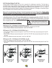
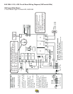
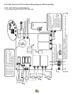
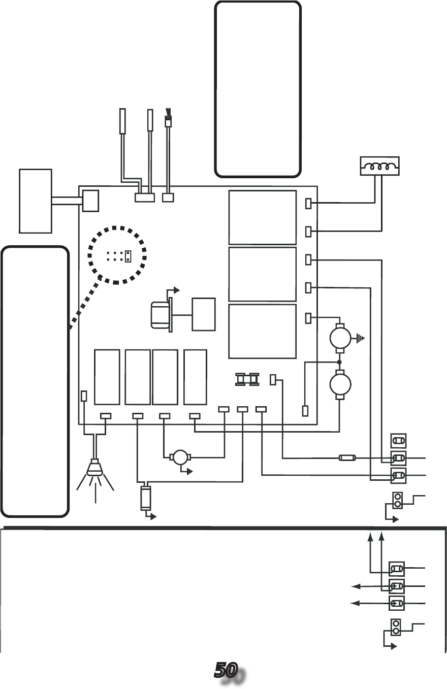
A9.0 2004 J-315, J-325 Circuit Board Wiring Diagram (US/Canada 60Hz)
US/Canada 60Hz Model
• Circuit Board Type: ProTech LED, 6600-086.
Ozonator
O
3
GRN
TB1
Standar
d 120 VA
C 3-Wire Connection
(60 Hz,
1 Phase,
15 A Service)
Use copper conductors ONLY.
Wire size must be
appropriate per NEC and/or local codes
.
WHT
WHT
WHT
WH
T
WHT
BLK
BLK
RED
BLK
BLK
BLK
BLK
BLK
RED
RED
RED
BLK
3
2
1
Heater
1.0 kW @ 120 VA
C
4.0 kW @ 240 VA
C
Flow Switch
Hi-limit/F
reez
e
Sensor
Temperature Sensor
J2
J3
F1
20A
250V
SC-20
Circ.
Pump
Main
Pump
Spa Light
Transformer
120 VA
C
J4
BLK
RED
*
GRN
TB1
WHT
BLK
RED
3
2
1
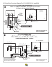
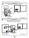
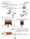
Optional 120/240 VAC
4-Wire Convertible
Heater Connection
1. Remove and discard the
factory installed GFCI Cord.
2.
Move RED
*
wire from TB1
position #1 to TB1 position #3
as shown below
.
3. Permanently connect to
the power supply
.
Use
copper conductors ONLY.
Wire size must be
appropriate per NEC and/or
local codes.
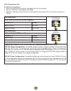
4. If hot tub is to be operated
on 30A service, make sure
the jumper provided at
location JP1 #1&2 on the
circuit board is installed. If
hot tub is to be operated on
40A service, remove the
jumper JP1 #1&2 on the
circuit board.
HI
LO
JP1
4
2
3
1
6 5
8 7
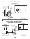
Logic Jumper Settings (Factory Defaults Shown)
JP1 1-2 ON = 15A
Logic (3-wire 120 V
AC operation only)
JP1 1-2 ON = 30A
Logic (4-wire 120/240 VAC operation only)
JP1 1-2 OFF = 40A
Logic (4-wire 120/240 V
AC operation only)
JP1 7-8 ON = ¡C
T
emperature Display
JP1 7-8 OFF = ¡F
T
emperature Display
This de
vice complies with Part
15 of the
FCC r
ules.
Operation is subject to the
follo
wing two conditions:
1.
This de
vice ma
y not cause har
mful
interf
erence
.
2.
This de
vice must accept an
y intef
erence
receiv
ed including interf
erence that ma
y
cause undesired operation.
J20
J21
J12
J14
J16
J11
J15
J13
J17 J7 J8
J9 J10
J5
J6
Heater IN
Heater OUT
F1*
K1
K2
K3
K4
K5 K7 K8
J1
Control
Panel