


27
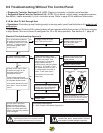
8.0 Troubleshooting Without The Control Panel
• Diagnostic Tools for Sections 8.1A - 8.1D: Clamp-on ammeter, voltmeter and ohmmeter.
• Suggested Spare Parts for Sections 8.1A - 8.1D: Circuit board, control panel, temperature sensor,
ow switch, heater assembly, hi-limit, circulation pump. Refer to page 59 for additional information.
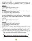
8.1A No Heat Or Not Enough Heat
• Symptoms: Circulation pump (heating pump) is moving water, panel heat indicator is lit. water is not
getting hot.
• Con guration: Protech LED system heaters will not operate with both jet pumps (J-345 only) running
in high speed if the circuit board is con gured for 30 or 50 Amp operation. See section 6.1, page 23.
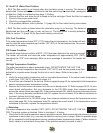
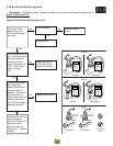
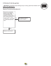
Standard Troubleshooting Approach
Replace or reconnect wires
between heater output and
heater element.
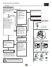
Circuit Board Illustrations
A. 2002+ Protech LED Models (Page 50-51)
Replace heater.
Replace Thermal Switch
Is voltage present at heater
input? Test points 4 and 5.
Replace or reconnect wires
between heater input relay
and TB1 (main power
terminal block).
Replace circuit board.
Place thermometer against heater
housing and verify temperature.
Is temperature above 130 F?
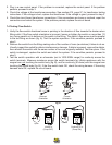
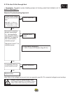
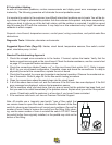
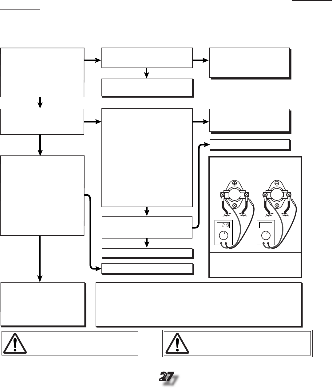
Locate thermal switch inside
heater box. Set voltage meter to
500-1000 VAC range. Test
thermal switch by connecting
voltage meter across the
terminals with a heat call present
(see fig. C). If 120 VAC* or 240
VAC exists, the switch is open. If
no voltage exists, the switch is
closed. Is the switch open?
*Convertible J315 and J325
models only
.
Is voltage present at heater
element? Test points 8 and 9.
No
No
No
No
Ye
s
**Call Technical Support
Yes
Yes
Ye
s
Ye
s
Current draw is proof that
heater element is working.
Make sure customer knows
how to use control panel and
heater. Ask about any possible
error messages.
Yes
No
No
Is there current draw? Refer
to section A3 (page 47) for
expected heater current
consumption values.
Check heater element with
clamp-on ammeter around one
of the heater element wires.
Is the heater element’s current
draw within –10% of its listed
value?
Turn up temperature setpoint
to initiate a heat call (must be
in "standard mode" F0-F3; see
page 21). Is voltage present
at the heater output? Test
points 6 and 7.
fig. C
Thermal Switch
Bad
Thermal Switch
Good
VAC
VA
C
Optional Test Method: you can also
remove one wire from either side of switch
and test across its terminals for continuity
.
Infinite =bad switch; 0 =good switch
Danger: Electrical Shock Hazard Exists!
High Voltage Present On Circuit Board. Use Ex-
treme Caution While Servicing Circuit Board.
**Warning: heater temperature may have ex-
ceeded 130ºF (54ºC). Inspect heater. Call tech-
nical support if visible damage is apparent.