


17
J-300
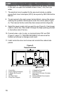
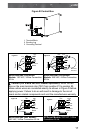
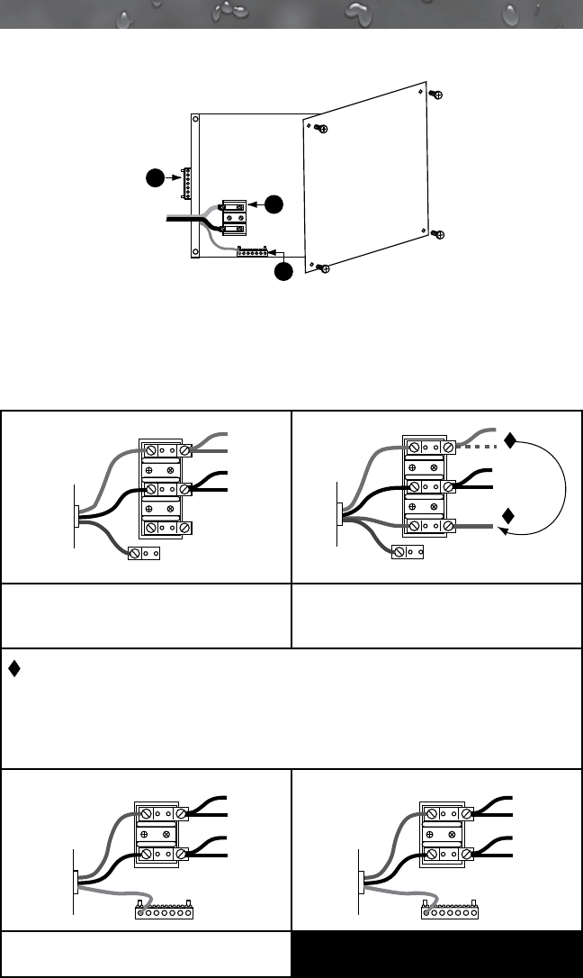
Figure B Control Box
TB1
3
2
1
1. Terminal Block
2. Bonding Lug
3. Grounding Terminal
GRN
WHT
WHT
BLK
BLK
BLK
RED
1
2
3
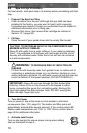
Figure-C
TB1
to Circuit
Board
Power In
GRN
WHT
WHT
BLK
BLK
BLK
RED
RED
RED
1
2
3
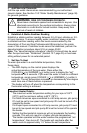
Figure-D
TB1
to Circuit
Board
Power In
Move Red
Wire Here
Models: 120 VAC, 3-Wire Connection
60 Hz
Models: 240 VAC, 4-Wire Connection
60 Hz
Caution (For 4-wire 240 VAC Heater Operation): Move the red
wire on the main terminal strip (TB1) from position #1 to position #3.
Make certain wires are connected exactly as shown in Figure D before
applying power. Failure to do so will result in damage to the circuit
board and/or related components and void the manufactures warranty.
BLK
RED
RED
RED
BLK
BLK
1
2
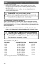
Figure-E
TB1
to Circuit
Board
Power In
Green
TB3
1
2
BLUE
BLUE
BROWN
BROWN
Figure-F
TB1
to Circuit
Board
Power In
Green
TB3
North American 240V Models:
240 VAC, 3-Wire Connection 60 Hz
All Export Models: 230 VAC, 3-Wire
Connection 50 Hz