


16
J-300
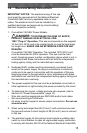
ANSI/NFPA 70. The disconnecting means must be readily accessible
to the spa’s occupant but installed at least 5 feet (1.5m) from spa
water.
7. The electrical circuit supplied for the spa must include a suitable
ground fault circuit interrupter (GFCI) as required by NEC/USA Article
680-42.
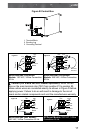
8. To gain access to the spa’s power terminal block, remove the screws
securing the synthetic cabinet panel under the control panel (Figure
A). Then remove the four control box door screws and door (Figure B).
9. Select the power supply inlet you want to use (Figure A). Feed power
cable to control box, then install it through the large opening provided
in the bottom side of the box.
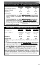
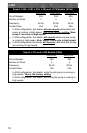
10. Connect wires, color to color, on terminal blocks TB1 and TB3
(Figure C, page 17). TIGHTEN SECURELY! All wires must be
hooked up securely or damage could result.
11. Install control box door and screws and reinstall the cabinet side
panels.
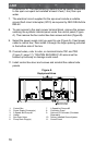
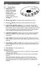
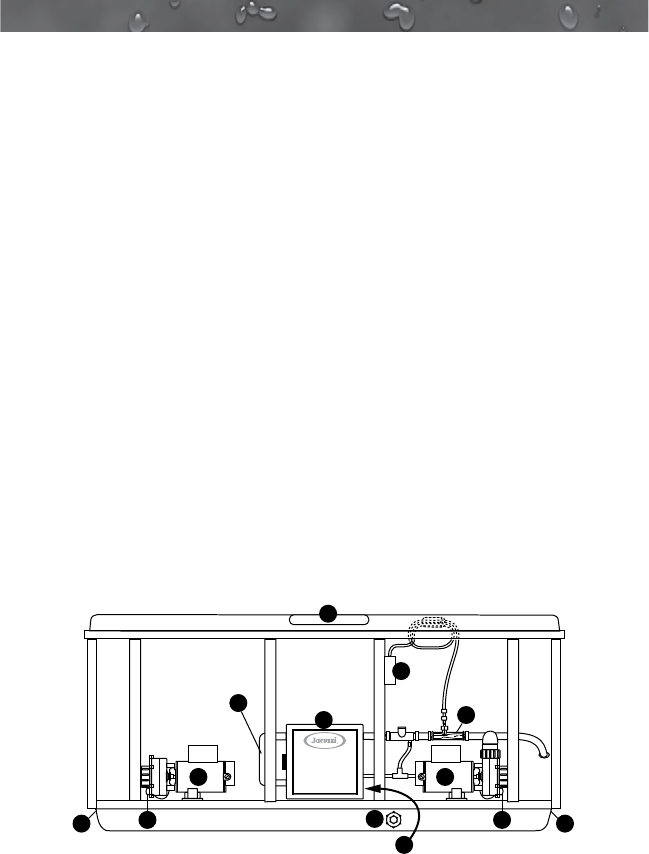
Figure A
Equipment Area
10
4
37
1
2 2
Flow
Note: Pump Locations Vary by Model
Circulation Pump
Behind Load Box
8
5
6 6
9
11
1. Control Box
2. Power Supply Entrance(s)
3. 2-Speed Jets Pump #1
4. Heater
5. Spa Drain Valve
6. Pump Drain Plugs(s)
7. 1-Speed Jet Pumps #2
8. Circulation Pump
9. Optional CD Ozonator (Purchase
Separately)
10. Factory Installed Ozone Injector
11. Control Panel