


Luxury Whirlpool Bath
Page 12 www.jacuzzi.com Installation and Operation
English
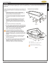
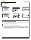
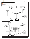
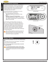
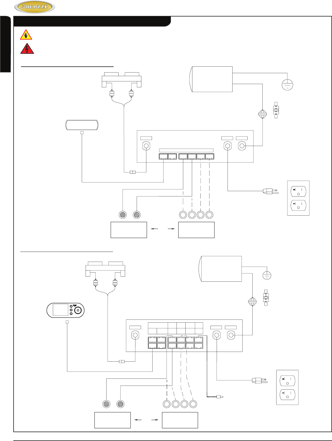
Reference Illustrations
These illustrations are for reference only, as the unit comes fully assembled.
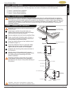
Risk of electric shock. Before servicing these connections, disconnect all power supply cables to both 120VAC
services.
J4 Control Panel Schematic Diagram
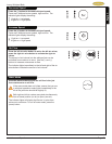
J5 Control Panel Schematic Diagram
CONTROL PANEL
CONTROL BOX
TEMPERATURE
SENSOR
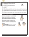
Air Valve
120 VAC
Pump
RS232
Panel
Blower
Inside
Light 1
Inside
Light 3
Ambient
Light 1
Temp
Sensor
Inside
Light 2
Inside
Light 4
LOGO
Light
Ambient
Light 2
LEAD CONNECTIONS
4-WHITE-C
3-BLACK-H
2-RED-L
1-GREEN-GRD
VIEW A
SEE VIEW A
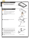
AIR VALVE ASSEMBLY
PUMP/MOTOR
CHROMETHERAPY
LIGHTS
ILLUMATHERAPY
LIGHTS
OR
1
2
3
4
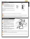
120VAC 20A
GFCI
1
2
3
4
CONTROL
PANEL
AIR VALVE ASSEMBLY
CHROMETHERAPY
LIGHTS
LEAD CONNECTIONS
4-WHITE-C
3-BLACK-H
2-RED-L
1-GREEN-GRD
VIEW A
SEE VIEW A
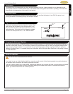
CONTROL BOX
Air Valve
120VAC
Pump
Panel
Blower
LED Light
PUMP/MOTOR
ILLUMATHERAPY
LIGHTS
OR
120VAC 20A
GFCI