


Luxury Whirlpool Bath
Installation and Operation www.jacuzzi.com Page 11
English
Electrical Connections
Risk of electric shock. Connect only to a circuit
protected by a GFCI.
When using electrical products, basic precautions
should always be followed:
•
Always follow local building and electrical codes.
•
Grounding is required. The unit should be
installed and grounded by a qualied electrician.
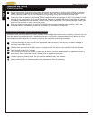
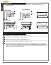
Two separate GFCI protected circuits are required.
A separate, 120VAC, 20 Amp GFCI circuit is required for
the pump/motor.
A separate, 120VAC, 15 Amp GFCI circuit is required for
the heater.
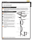
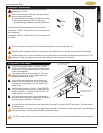
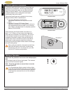
Reset
Test
1
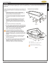
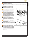
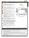
For the pump/motor, install a 120 VAC, 20AMP,
GFCI duplex outlet to the stud wall underneath the
bathtub at 4˝ (101mm) above the oor. The duplex
outlet is not supplied.
Pump/Motor and Heater
The duplex outlet must be mounted 4˝ (101mm)
above the oor line, or in accordance with local
building and electrical codes.
Risk of component overheat. Do not use electric extension cord to power this unit.
Operating the motor/pump without enough water in the bathtub can cause leaking and permanent damage.
At initial startup, the 7 button electronic control system enters an automatic self diagnostic program for 15-20
seconds. During the diagnostic program, the system will not accept user commands.
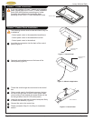
2
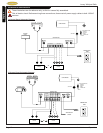
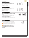
Using a #8 solid copper wire, ground the pump
motor to the house electrical panel, or approved
local ground. A grounding lug is provided on the
pump motor
3
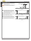
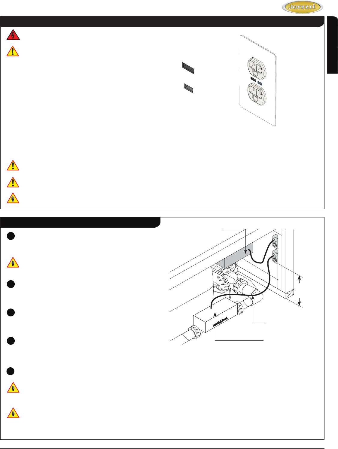
For the heater, install a 120VAC, 15 AMP RATED
GFCI single outlet to the wall stud underneath the
bathtub, at least 4˝ (101mm) above the oor. The
single outlet is not provided.
4
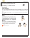
With a #8 solid copper wire, ground the heater to
the house electrical panel or approved local bond. A
grounding lug is provided on the heater.
Push this button in to reset. If the interrupter fails to operate in this manner, there is a ground current owing or a
device malfunction, indicating the possibility of electrical shock.
Turn OFF power and do not use the bathtub until the source of the problem has been identied and corrected.
4˝
(101mm)
Heater
Power Cord from Heater
Box to GFCI Circuit
Power Cord from Control
Box to GFCI Circuit
5
At initial start-up, and before each use thereafter with power ON, push the GFCI test button. The reset button
should pop out.
T
M