


9-20 333559 09/08
Adjustments
Introduction
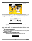
Your FasTrak 36/42 was adjusted before it left the factory and was checked during pre delivery setup. How-
ever, after start-up and continued use, a certain amount of break-in wear will cause some adjustments to
change.
Remain alert for unusual noises, they could be signaling a problem.Visually inspect the machine for any
abnormal wear or damage. A good time to detect potential problems is while performing scheduled mainte-
nance service. Correcting the problem as quickly as possible is the best insurance.
Clear away heavy build-up of grease, oil and dirt, especially in the engine and under the seat platform
areas; minute dust particle are abrasive to close-tolerance engine and hydraulic assemblies.
Some repairs require the assistance of a trained service mechanic and should not be attempted by
unskilled personnel. Consult your Hustler service center when assistance is needed.
Park Brake Adjustment
Occasionally check the park brake adjustment using the following method:
1. Shut engine off, place control levers in the park brake position, disengage deck clutch,
remove ignition switch key and disconnect negative battery cable before doing any
adjustments.
2. Raise and block the tractor up so the drive wheels are off of the floor.
WARNING:
Never work under the machine or attachment unless it is safely supported with jack
stands. Make certain machine is secure when it is raised and placed on the jack stands. The jack
stands should not allow the machine to move when the engine is running and the drive wheels are
rotating. Use only certified jack stands. Use only appropriate jack stands, with a minimum
weight rating of2000 pounds to block the unit up. Use in pairs only. Follow the instructions
supplied with the vehicle stands.
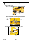
3. Remove the drive tires.
4. Push the steering lever inward into the operating position, disengaging the brake.
Only adjust one side at a time.
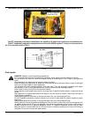
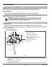
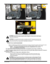
5. Locate the brake lever arm and brake gear on the EZT transmission.When the
steering lever is in the operating position, the brake arm should have a minimum of
0.06" (1.52MM) and maximum of 0.125"(3.18MM) clearance between the teeth of the
brake lever arm and the outside diameter of the brake gear (FIG. 21).
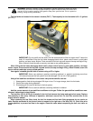
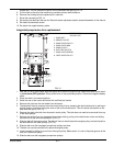
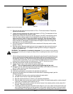
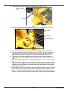
6. If you find that the clearance is not to this specification, then adjust the position of the
brake lever arm by moving the lock nuts on the brake rod accordingly. When
adjusting the nuts, the spacing between the inside of the nuts needs to be maintained
at 7/8"(2.22CM) which has been set at the factory. The best way to keep this spacing
is to turn both nuts in the same direction the same number of turns (FIG. 22).
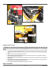
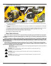
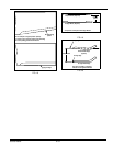
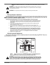
7. Loosen the jam nut on the brake rod and rotate the adjusting tube (FIG. 23) until the
dimensions shown in Fig. 9-18 can be attained.Re-tighten the locknut.
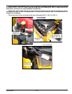
8. After adjustments are made and the proper clearance is restored, actuate and release
the brakes with the steering lever several times.Check to make sure the brake arm on
the EZT is engaging and fully disengaging the teeth of the brake gear.
9. Repeat this process for the opposite side if required.
10. Assemble the rear tires and re-torque the lug nuts to 65-75 ft.-lbs.(88.14-101.7 NM)
11. Raise the rear of the tractor and remove the jack stands. Lower the tractor.
Steering linkage adjustment
The neutral adjustment has been factory adjusted to eliminate creeping when the control levers are in the
neutral position. However, if the steering linkage should ever need adjustment due to the unit creeping
when the steering levers are in the neutral position or the EZT’s whining when the parking brakes are
engaged, take the unit to an Authorized Hustler Dealer for adjustment.