9-16 333559 09/08
Engine mounting bolts
If the original engine mounting bolts are ever removed from the tractor, do not reuse. The original bolts are
self-tapping and if they are re-used they may try to cut new treads into the engine block mounting holes.
Replace with 3/8"-16 x 1.00 Grade 5 bolts. Apply Loc-Tite® 242 to the treads and torque to 30-35 ft.-lbs. Re-use
thin int/ext tooth lockwashers that were factory installed with the original mounting bolts.
Belt replacement
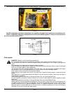
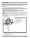
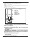
FIG. 14 and FIG. 15 show diagrams and descriptions of the unit’s belt drive systems.
Inspect these belts frequently for wear and serviceability. Replace a belt that shows signs of severe cuts,
tears, separation, weather checking and cracking, or burns caused by slipping. Slight raveling of belt covering
does not indicate failure, trim ravelling with a sharp knife.
WARNING:
If the pump belt fails, loss of control will occur especially when operating on a slope.
If you lose steering control while operating the machine, place the steering control levers
in the park brake position immediately. Inspect the machine and involve your Hustler
dealer to resolve the problem before continuing to operate.
Inspect the belt pulley grooves and flanges for wear. A new belt, or one in good condition, should never
run against the bottom of the groove. Replace the pulley when this is the case, otherwise belt will lose power
and slip excessively.
Never pry a bolt to get it on a pulley as this will cut or damage the fibers of the belt covering.
Keep oil and grease away from belts, and never use belt dressings. Any of these will destroy the belt com-
position in a very short time.
Deck belt replacement
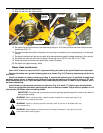
1. Park the unit on a flat surface. Stop the engine and remove the ignition key. Make sure deck clutch switch
is in the down (OFF) position. Place control levers in the park brake position. Disconnect negative
battery cable.
2. Place the deck in the lowest position.
3. Remove the deck belt covers.
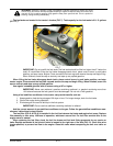
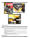
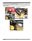
4. Release the deck belt tension by pulling on the belt tension chain and sliding the chain out of the anchor
DECK BELT DRIVE LAYOUT
1. SPINDLE DRIVE BELT
2. DECK BLADE SPINDLE PULLEY
3. SPINDLE BELT TENSION IDLER
4. SPINDLE BELT TENSION IDLER SPING
(7.5" AT OPERATION)
5. DECK BELT IDLER PULLEY
6. IDLER ARM
FIG. 14
1
2
2
3
4
5
6


