601396_0109 4-5
the throttle and/or engaging the deck clutch.
9. Before stopping the engine, place the steering control
levers in the park brake position, disengage the deck
clutch, and throttle back to low idle for a couple of
minutes; then rotate ignition key counter-clockwise to the
OFF position. Remove the key from switch before
leaving the tractor.
Stopping the engine
Use the following procedure to shut off the engine after
operating the equipment.
1. Place the steering control levers in the park brake
position
2. Disengage the deck clutch
3. Throttle back to low idle for a couple of minutes
4. Rotate ignition key counter-clockwise to the OFF
position. Remove the key from switch before leaving the
tractor.
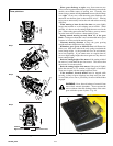
Moving tractor with stalled engine
If it becomes necessary to move the tractor when the engine is
inoperative, the transaxles are equipped with bypass valves.
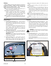
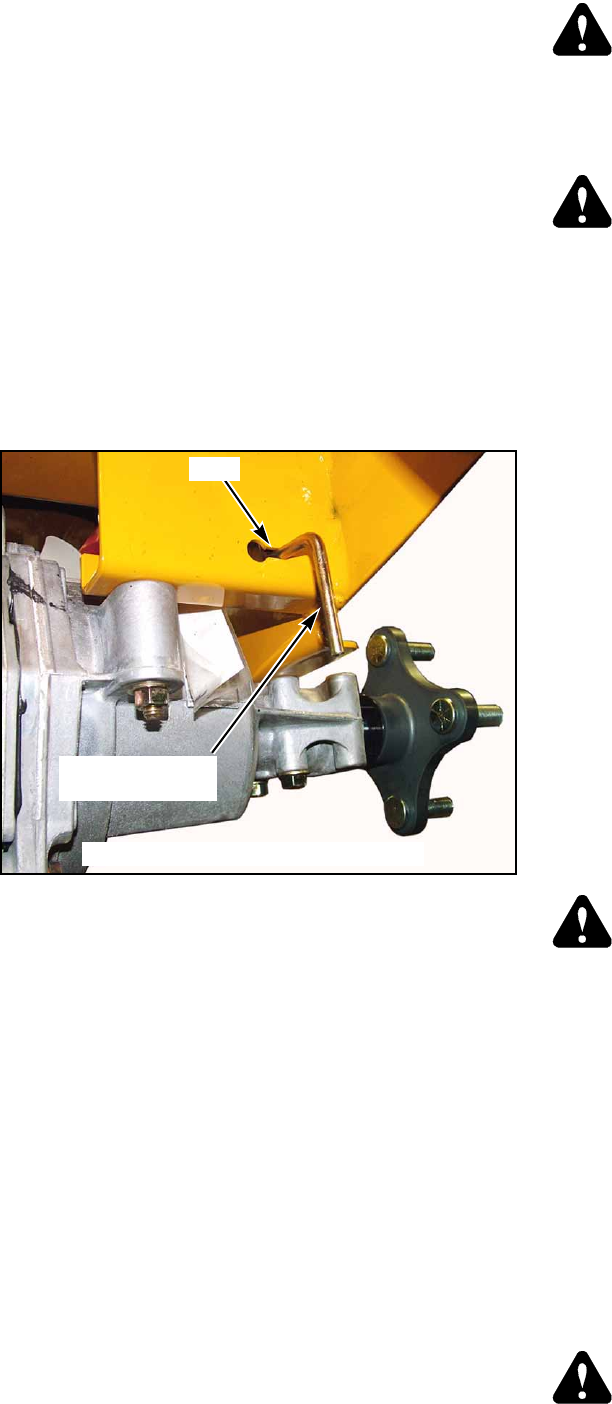
Before moving the unit, pull out on the bypass valve rods and
slide them into the slot to lock in position. Both bypass valve
rods are located underneath the rear of the tractor at the back of
the transaxle. (Fig. 4-5)
The steering control levers must be placed in the neutral
position, to release the park brakes, so that the tractor can be
moved.
Do not tow the machine. Move it by hand or use a winch to
load on a trailer for transporting.
When transporting on another vehicle, the tractor must be
secured.
IMPORTANT: Always make certain the two bypass valves
are returned to their operating position before running the trac-
tor following repairs.
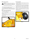
WARNING: Allow engine exhaust manifold to cool
before engaging or disengaging the bypass valves.
The bypass valve rods are located close to the exhaust
system.
Driving the tractor
DANGER: Never make sudden stops or reverse
direction, especially when maneuvering on a slope.
The steering is designed for sensitive response. Rapid
movement of the steering control levers in either
direction could result in a reaction of the tractor that
can cause serious injury.
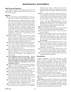
After starting engine, engage the control levers and steer as
follows:
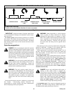
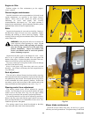
To go forward, push steering control levers forward an equal
distance (Fig. 4-6).
To go in reverse, pull steering control levers rearward an
equal distance (Fig. 4-6).
To turn left, move the right steering control lever farther
forward from neutral than the left steering control lever.
(Fig. 4-6)
To turn right, move the left steering control lever farther
forward from neutral than the right steering control lever.
(Fig. 4-6)
“0” degree turn, move one steering control lever forward and
the other steering control lever back of neutral. This will allow
the drive wheels to counter-rotate. (Fig. 4-6)
To stop or decrease speed, move steering control levers to
neutral. When going forward pull back gently on steering
control levers. When going in reverse push forward gently on
steering control levers.
For emergency stop, when traveling forward or rearward,
place the steering control levers in the park brake position
immediately.
DANGER: When moving in the rearward direction
push forward gently on steering control levers and
avoid sudden movement. Any sudden movement
could cause the front of the mower to come off of the
ground resulting in possible loss of control causing
serious injury or death.
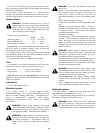
To make a three point turn to the right, move the left
steering control lever farther forward from neutral than the right
steering control lever and start the turn. Next, pull back on the
steering control levers until they are past neutral and the
machine starts to go rearward. Pull right steering control lever
farther rearward from neutral than the left steering control lever
until the rear of the machine has pivoted around. Then, push the
steering control levers forward until they are both past neutral
and the machine starts to go forward. Push the left steering
control lever farther forward from neutral than the right steering
control lever and finish the turn. (Fig. 4-7)
WARNING: Always be aware of what is behind the
machine before backing up. Do not mow in reverse
unless absolutely necessary. Always look down and
behind before and while backing up.
Fig. 4-5
Slot
Bypass valve rod
(Right rod shown)
(Viewed from the rear right underneath side)


