


8
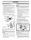
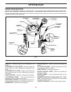
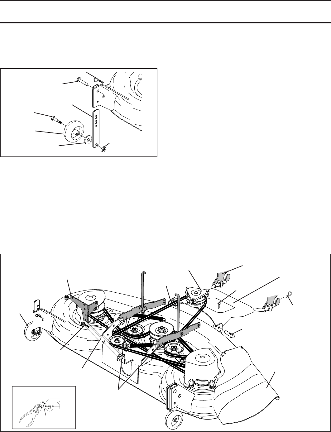
SHOULDER
BOLT
AD JUST ING
BAR
PIN
RETAINER SPRING
FIG. 5
GAUGE
WHEEL
3/8-16 CENTER
LOCKNUT
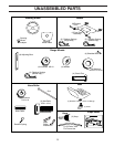
ASSEMBLY
3/8 WASH ER
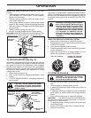
• For ease of mower to tractor assembly, raise gauge
wheels to highest position and retain with clevis pins
and spring retainers.
• Adjust gauge wheels before operating mower. See “TO
ADJUST GAUGE WHEELS” in the Operation sec tion
of this manual.
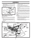
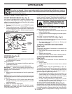
INSTALL MOWER AND DRIVE BELT
(See Figs. 6 and 7)
Be sure tractor is on level surface and mower suspension
arms are raised with attachment lift control. Engage park-
ing brake.
• Cut and remove ties securing anti-sway bar and belts.
Swing anti-sway bar to left side of mower deck.
• Slide mower under tractor with defl ector shield to right
side of tractor.
IMPORTANT: Check belt for proper routing in all mower
pulley grooves.
• If equipped, turn height ad just ment knob coun ter -
clock wise until it stops.
• Lower mower linkage with attachment lift control.
• Install belt into electric clutch pulley groove.
• Place the suspension arms on outward pointing deck
pins. Retain with double loop re tain er spring with loops
up as shown.
• Install front plate assembly to tractor suspension
brack ets and retain with single loop retainer springs
as shown.
• Position front plate assembly between front mower
brack ets. Raise deck and plate assembly to align holes
and insert fl anged pins. Secure pins with double loop
retainer springs between the plate and mower brack-
ets.
NOTE: To assist in locating hole in fl anged pin, the hole in
pin is inline with notch on head of pin. If necessary, move
mower side-to-side to give space between plate and mower
brackets.
IMPORTANT: Check belt for proper routing in all mower
pulley grooves.
• Connect anti-sway bar to chassis bracket under left
foot rest and retain with double loop retainer spring.
• If equipped, turn height adjustment knob clock wise to
remove slack from mower sus pen sion.
• Raise deck to highest position.
• Adjust gauge wheels before op er at ing mower as shown
in the Operation section of this manual.
FIG. 6
02509
ANTI-SWAY
BAR
SINGLE
LOOP
RETAINER
SPRINGS
GAUGE
WHEEL
SUSPENSION
ARMS
DOUBLE LOOP
RETAINER SPRING
FRONT SUS PEN SION BRACKETS
FRONT
PLATE
AS SEM BLY
CHASSIS
BRACKET
DOUBLE LOOP RETAINER
SPRING (OUTWARD POINTING
DECK PINS)
ELECTRIC
CLUTCH PULLEY
DE FLEC TOR
SHIELD
FRONT
MOWER
BRACKET
FLANGED PIN
DOUBLE LOOP
RE TAIN ER
SPRING
USE PLIERS FOR
RETAINER SPRINGS
LOOP UP