


23
SERVICE AND ADJUSTMENTS
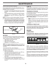
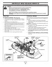
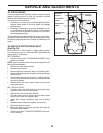
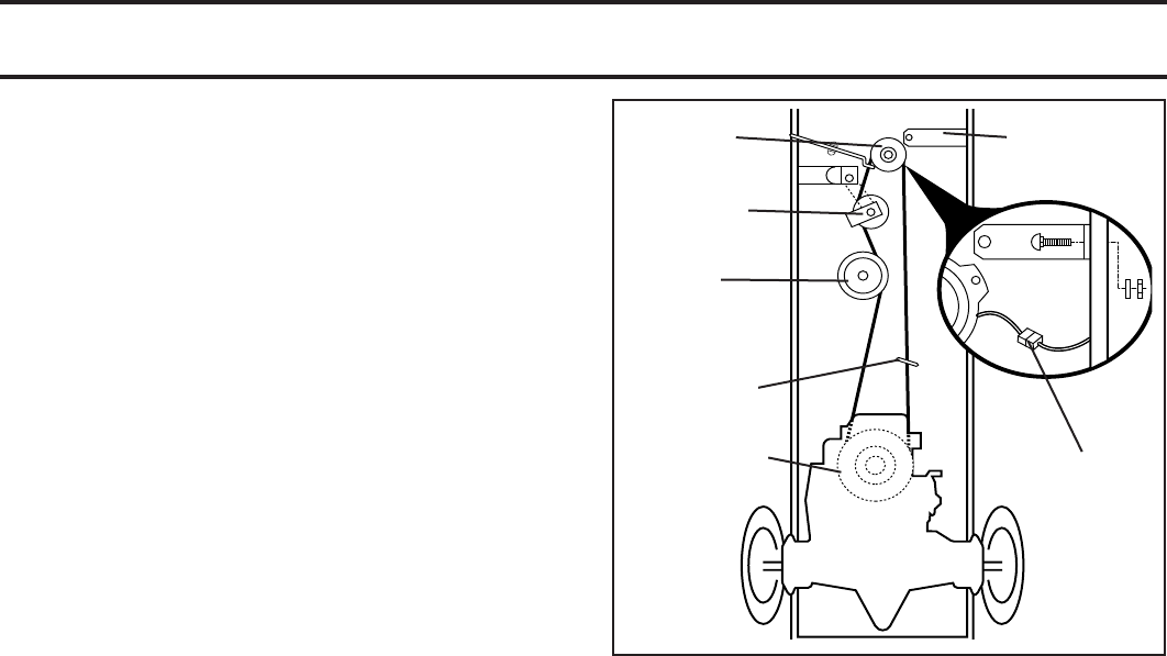
TO REPLACE MOTION DRIVE BELT
(See Fig. 26)
Park the tractor on level surface. En gage parking brake.
For as sis tance, there is a belt installation guide decal on
bottom side of left footrest.
BELT REMOVAL -
• Remove mower (See “TO RE MOVE MOWER” in this
section of manual).
NOTE: Observe entire motion drive belt and position of all
belt guides and keepers.
• Disconnect clutch wire harness.
• Remove clutch locator.
• Remove belt from stationary idler and clutching idler.
• Remove belt downward from engine pulley and around
electric clutch.
• Pull belt slack toward rear of trac tor. Carefully remove
belt up wards from trans mis sion input pulley and over
cooling fan blades.
• Remove belt from center span keeper and pull belt
away from tractor.
BELT INSTALLATION -
• Carefully work new belt down around transmission
cool ing fan and onto the input pulley.
• Slide belt into the center span keeper.
Pull belt toward front of tractor and roll belt around
electric clutch and onto engine pulley.
• Install belt through stationary idler and clutch ing
idler.
• Reinstall clutch locator and tighten nut securely.
• Reconnect clutch harness.
• Make sure belt is in all pulley grooves and in side all
belt guides and keep ers.
• Install mower (See “TO IN STALL MOWER” in this sec-
tion of manual).
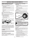
TO CHECK BRAKE
If tractor requires more than fi ve (5) feet to stop at highest
speed in high est gear on a level, dry concrete or paved
surface, then brake must be serviced.
You may also check brake by:
1. Park tractor on a level, dry concrete or paved surface,
depress brake pedal all the way down and engage
parking brake.
2. Disengage transmission by placing freewheel control
in “transmission disengaged” position. Pull freewheel
control out and into the slot and release so it is held in
the disengaged position.
The rear wheels must lock and skid when you try to manu-
ally push the tractor forward. If the rear wheels rotate, then
the brake needs to be serviced. Contact a qualifi ed service
center.
FIG. 26
01511
CLUTCH
LOCATOR
CLUTCH
WIRE
HAR NESS
STATIONARY
IDLER
TRANS MIS SION
INPUT PULLEY
CLUTCH ING
IDLER
ELECTRIC
CLUTCH
CENTER SPAN
KEEPER