


21
SERVICE AND ADJUSTMENTS
FIG. 20
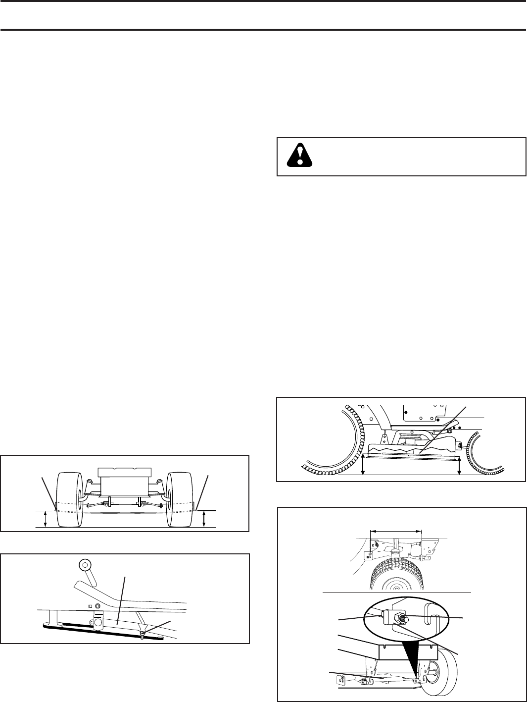
FIG. 21
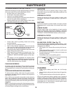
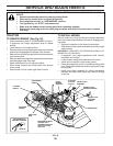
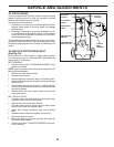
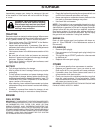
FRONT-TO-BACK ADJUSTMENT (See Figs. 21 and 22)
IMPORTANT: DECK MUST BE LEVEL SIDE-TO-SIDE. IF THE
FOLLOWING FRONT-TO-BACK AD JUST MENT IS NECESSARY,
BE SURE TO ADJUST BOTH FRONT LINKS EQUALLY SO
MOWER WILL STAY LEVEL SIDE-TO-SIDE.
To obtain the best cutting re sults, the mower blades should
be adjusted so the front tip is ap prox i mate ly 1/8" to 1/2"
lower than the rear tip when the mower is in its highest
position.
CAUTION: Blades are sharp. Protect
your hands with gloves and/or wrap
blade with heavy cloth.
Check adjustment on right side of trac tor. Position any blade
so the tip is pointing straight forward. Measure distance "B"
at front and rear tip of the blade.
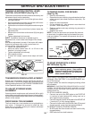
• Before making any necessary ad just ments, check that
both front plate links are equal in length.
• If links are not equal in length, adjust one link to same
length as other link.
• To lower front of blade, loosen nut “C” on both front
links an equal number of turns.
NOTE: Each full turn of nut “C” will change distance. “B”
by approximately 3/16".
• When distance “B” is 1/8" to 1/2" lower at front than rear,
tighten nut “D” against trunnion on both front links.
• To raise front of blade, loosen nut “D” from trunnion on
both front links. Tighten nut “C” on both front links an
equal number of turns. The two front links must remain
equal in length.
• When distance “B” is 1/8" to 1/2" lower at front than rear,
tighten nut “D” against trunnion on both front links.
• Recheck side-to-side adjustment.
01553
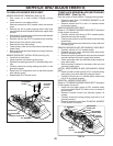
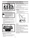
SUSPENSION
ARM
LIFT LINK
AD JUST MENT NUT
02548
“B”
“B”
BLADE
02517
BOTH FRONT PLATE LINKS MUST BE
EQUAL IN LENGTH
TRUN NION
FRONT PLATE
AS SEM BLY
NUT “C”
NUT “D”
02516
FIG. 22
TO LEVEL MOWER HOUSING
Adjust the mower while tractor is parked on level ground
or driveway. Make sure tires are properly infl ated (See
“PROD UCT SPECIFICATIONS” section of this manual). If
tires are over or underinfl ated, you will not properly adjust
your mower.
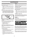
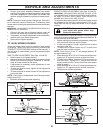
SIDE-TO-SIDE ADJUSTMENT (See Figs. 19 and 20)
• Raise mower to its highest position.
• Measure height from bottom edge of mower to ground
level at front cor ners of mower. Distance “A” on both
sides of mower should be the same.
• If adjustment is necessary, make adjustment on one
side of mower only.
• To raise one side of mower, tighten lift link ad just ment
nut on that side.
• To lower one side of mower, loosen lift link ad just ment
nut on that side.
NOTE: Each full turn of adjustment nut will change mower
height about 3/16".
• Recheck measurements after ad just ing.
00598
GROUND LINE
BOTTOM EDGE
OF MOWER TO
GROUND
BOTTOM EDGE
OF MOWER TO
GROUND
AA
• Position front plate assembly between front mower
brackets. Raise deck and plate assembly to align holes
and insert fl anged pins. Secure pins with double loop
retainer springs between the plate and mower brack-
ets.
NOTE: To assist in locating hole in fl anged pin, the hole in
pin is inline with notch on head of pin. If necessary, move
mower side-to-side to give space between plate and mower
brack ets.
IMPORTANT: CHECK BELT FOR PROPER ROUTING IN ALL
MOWER PULLEY GROOVES.
• Connect anti-sway bar to chassis bracket under left
foot rest and retain with double loop retainer spring.
• If equipped, turn height adjustment knob clock wise to
remove slack from mower sus pen sion.
• Raise deck to highest position.
FIG. 19