


11
8
Starting up
Disconnect the machine by
unplugging the supply cable.
Disconnect the plug.
Store in a dry place, not
accessible to children.
Maintain the tools carefully.
"Engine Maintenance" : refer to
the engine maintenance booklet.
Dispose of the old oil as laid
down by the regulations in force.
Always pay extreme care and
attention to the preparation of
the machine before starting up.
9
Cutting method
Remove all adjustment tools and
wrenches from floor and
machine
Always keep blade guard in
place.
The disc locking nut has a left-
hand thread.
Take care about the direction of
rotation which is shown by an
arrow on one of the faces.
Make sure the contact faces of
flanges, of blade and the axle are
clean.
- Make sure that the mains
voltage corresponds with that
marked on the manufacturer's
plate on the machine.
- Three-phase motor
Make sure that the motor rotates
in the same direction as the
arrow stamped on the casing: if
the motor does not turn in the
direction required, swap two of
the supply wires.
• Loosen the clamping nut using the
360Xmm spanner.
- Extension lead : Cable size sufficient for
the electrical power, connection to the
mains by a H07 RNF type cable of the
following size:
- 3 x 2.5 mm
2
up to 50 m for 230 V
- 5 x 1.5 mm
2
up to 100 m for 400 V
- 3 x 4 mm
2
up to 40 m for 115 V
• Fill the water tank (maximum level at the
bottom of the rails).
• The water pump starting is coupled with
that of the motor.
As each machine is fitted with a self
priming pump, the water is sprayed
onto the disc as soon as the machine
starts.
The protective case and the motor
mounting fitted with a deflector blade
provide perfect distribution of the spray.
• Place the material on the table. Hold it
with both hands. Push the pedal and then
the material towards the blade.
• According to the material thickness and
hardness, the cut should be carried in
one or several passes.
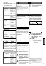
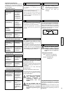
• Millimetric adjustments : do as above,
then turn the second wheel (J) one way
or the other (a maximum of 5 turns) to
obtain the required adjustment.
• For identical depth cuts, release the lever
(K). Press the pedal or handle to the
depth required. Tighten the lever (A). The
head can then only come up to the depth
set.
• To maintain the cutting depth, clamp with
the wheel (B).
• To set to a different depth of cut, release
the lever (K).
11
Maintenance (the motor must be
stopped)
• Clean the machine regularly.
• Drain the tank frequently to remove
cutting residue, which otherwise could
block the pump and cause it to wear out
prematurely.
• Wash out the tank with plenty of water.
• Carefully clean the contact faces for the
table rollers.
• If, after a period of use, the cutting head
does not return to its initial position (top
position), tighten the nut a few turns to
increase the tension on the head return
spring [SEE EXPLODED VIEW].
• Petrol engine
Refer to the manufacturer's operating
manual.
• Petrol engine
Turn off on the speed control.
• Remove the locking flange.
• Fit the disc.
• Tighten the nut.
• Refit the protective case.
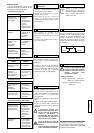
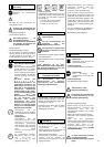
• To mount a disc larger than 500 mm (fig. 5)
remove screw A to release spindle B.
Fold the disc cover backwards.
7
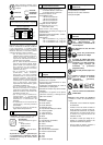
Electrical connection
- ELECTRICAL SAFETY :
Operate this machine only on a
supply equipped with a 30 mA
earthed current-limiting circuit-
breaker. Otherwise, consult our
catalogue for appropriate models.
- The RCCB must be used
correctly, including testing it
regularly. For tools supplied
with an integral RCCB in the
cable or in the mains plug, if
the cable or plug has been
damaged, repairs must be
carried out by the
manufacturer, one of his
agents or by a qualified repair
workshop to avoid any risks
resulting from errors.
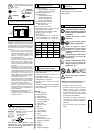
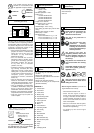
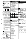
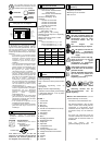
- Use the following types of plug,
single phase 2 P + E, or
3xPx+xE / 3xPx+xNx+xE
according to the corresponding
voltage.
2 P + T
230 V
H07 - RNF
3 x 2,5
2
50 M
+ (x2)
400 V
H07 - RNF
5 x 1,5
2
100 M
+ (x2)
110 V
H07 - RNF
3 x 4
2
40 M
+ (x2)
●●
●●
Ensure that the water supply is
abundant, when cutting wet.
• Electric motor
Start by pressing the circuit
breaker.
• Electric motor
To stop the machine, press the
red button.
• The weight of the head, being
compensated by springs, is designed so
that slight pressure applied by the user is
enough to cut material.
• Locking the head : release the stop lever
(K), press the pedal to set the disk to the
required depth and lock.
10
Dept adjustment
[VEASE FIG. 5]
English
6
Fitting the disc
[VEASE FIG. 3]