


ASSEMBLY
8
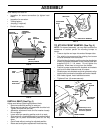
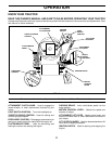
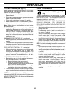
TO ATTACH NOSE ROLLER (See Fig. 6)
• Position brackets, 17/32 x 7/8 x 16 gauge washers, and
nose roller between deck mounting brackets as shown.
Be sure to position brackets on correct side, as shown.
• Install 3/8-16 x 1 hex bolts and 3/8-16 crownlock nuts
as shown. Tighten hardware securely.
NOTE: Be sure bracket tabs are positioned in tab holes in
deck brackets.
NOSE ROLLER
HEX
BOLT
“B”
BRACKET
TAB
TAB HOLE
CROWNLOCK
NUT
“A” BRACKET TAB
WASHER
FIG. 6
FIG. 7
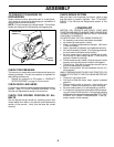
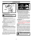
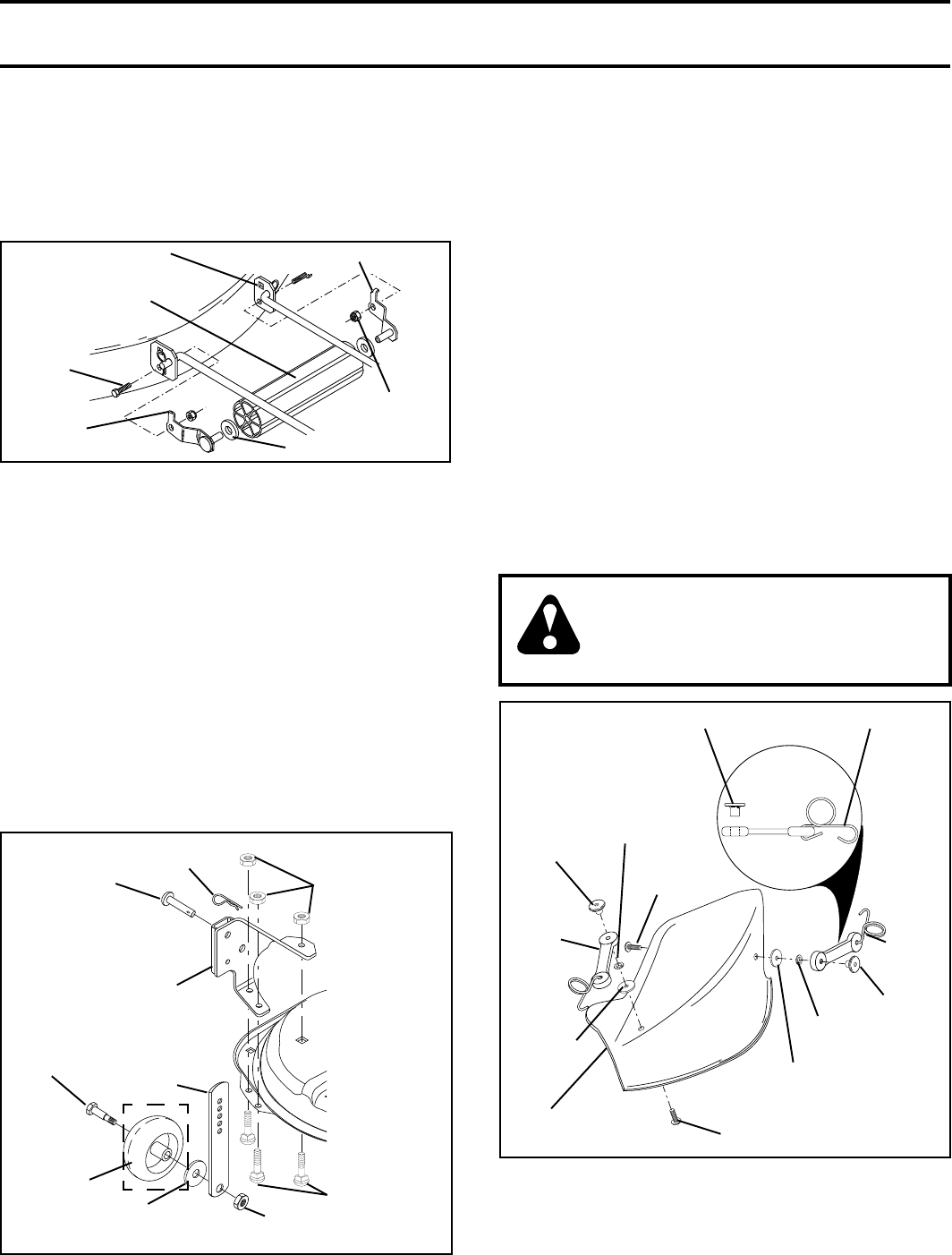
INSTALL MULCHER PLATE
(See Figs. 8 and 9)
• Install two latch hooks to mulcher plate using screw,
washer, lock washer, and weld nut as shown.
NOTE: Pre-assemble weld nut to latch hook by inserting
weld nut from the top with hook pointing down.
• Tighten hardware securely.
• Raise and hold deflector shield in upright position.
• Place front of mulcher plate over front of mower deck
opening and slide into place, as shown.
• Hook front latch into hole on front of mower deck.
• Hook rear latch into hole on back of mower deck.
CAUTION: Do not remove discharge
guard from mower. Raise and hold
guard when attaching mulcher plate
and allow it to rest on plate while in
operation.
LATCH
HOOK
WELD
NUT
SCREW
LOCK
WASHER
WASHER
WASHER
FIG. 8
HOOK POINTS DOWN
WELD NUT FROM THE TOP
WELD
NUT
SCREW
LOCK
WASHER
MULCHER
PLATE
LATCH
HOOK
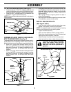
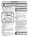
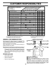
ASSEMBLE GAUGE WHEELS AND BRACK-
ETS TO MOWER DECK (See Fig. 7)
The gauge wheels are designed to keep the mower deck in
proper position when operating mower. Be sure they are
properly adjusted to ensure optimum mower performance.
• Attach front gauge wheel brackets marked front left
(FL), front right (FR) to mower deck using (3) carriage
bolts and (3) locknuts. For ease of installation do not
tighten locknuts until all carriage bolts have been
installed.
• Attach rear gauge wheel brackets marked rear left (R
L), rear right (RR) to mower deck using (3) carriage
bolts and (3) locknuts. For ease of installation do not
tighten locknuts until all carriage bolts have been
installed.
SHOULDER
BOLT
GAUGE
WHEEL
3/8-16 CENTER
LOCKNUT
GAUGE
WHEEL
MOUNTING
BRACKET
3/8 WASHER
CARRIAGE
BOLTS
CROWNLOCK
NUT
ADJUSTING
BAR
PIN
RETAINER
SPRING
• Slide gauge wheel bar down into bracket channel, Be
sure that gauge wheel bar aligning holes are on top.
Assemble gauge wheels as shown using shoulder
bolts, 3/8 washers and 3/8-16 center locknuts and
tighten securely.
• Adjust gauge wheels to highest position for ease of
mower deck assembly.
• Adjust gauge wheels before operating mower as shown
in the operation section of this manual.