


SERVICE AND ADJUSTMENTS
21
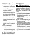
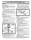
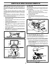
MANDREL
"D"
"D"
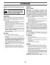
FIG. 24
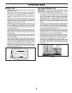
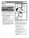
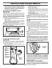
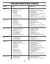
BOTH FRONT LINKS MUST BE EQUAL IN LENGTH
NUT "E"
NUT "F"
TRUNNION
FRONT LINKS
FIG. 25
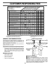
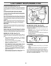
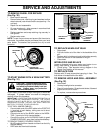
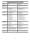
TO REPLACE MOWER BLADE DRIVE BELT
(See Fig. 26)
The mower blade drive belt may be replaced without tools.
Park the tractor on level surface. Engage parking brake.
BELT REMOVAL -
• Remove mower from tractor (See “TO REMOVE
MOWER” in this section of this manual).
• Work belt off both mandrel pulleys and idler pulleys.
• Pull belt away from mower.
BELT INSTALLATION -
• Install new belt in reverse order of removal.
• Make sure belt is in all pulley grooves and inside all belt
guides.
• Install mower in reverse order of removal instructions.
MANDREL PULLEY
IDLER
PULLEYS
MANDREL
PULLEY
FIG. 26
FRONT-TO-BACK ADJUSTMENT (See Figs. 24 and 25)
IMPORTANT: DECK MUST BE LEVEL SIDE-TO-SIDE. IF
THE FOLLOWING FRONT-TO-BACK ADJUSTMENT IS
NECESSARY, BE SURE TO ADJUST BOTH FRONT LINKS
EQUALLY SO MOWER WILL STAY LEVEL SIDE-TO-
SIDE.
To obtain the best cutting results, the mower housing
should be adjusted so that the front is approximately 1/8" to
1/2" lower than the rear when the mower is in its highest
position.
Check adjustment on right side of tractor. Measure dis-
tance “D” directly in front and behind the mandrel at bottom
edge of mower housing as shown.
• Before making any necessary adjustments, check that
both front links are equal in length. Both links should be
approximately 10-3/8".
• If links are not equal in length, adjust one link to same
length as other link.
• To lower front of mower loosen nut “E” on both front
links an equal number of turns.
• When distance “D” is 1/8" to 1/2" lower at front than
rear, tighten nuts “F” against trunnion on both front
links.
• To raise front of mower, loosen nut “F” from trunnion on
both front links. Tighten nut “E” on both front links an
equal number of turns.
• When distance “D” is 1/8" to 1/2" lower at front than
rear, tighten nut “F” against trunnion on both front links.
• Recheck side-to-side adjustment.
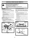
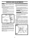
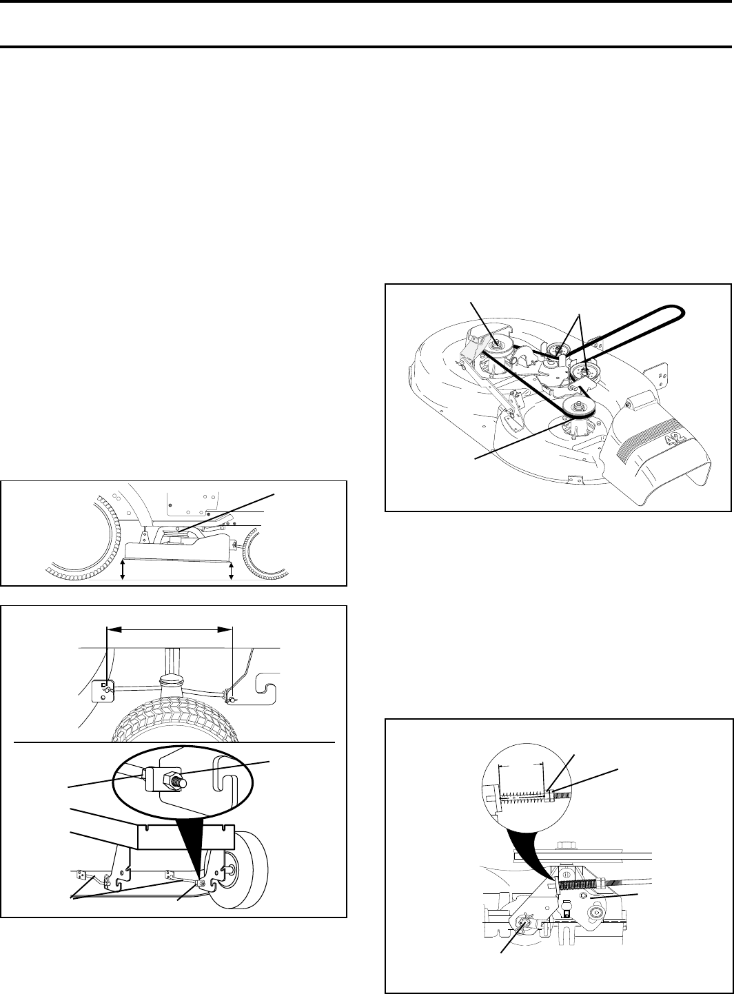
TO ADJUST BRAKE (See Fig. 27A)
Your tractor is equipped with an adjustable brake system
which is mounted on the side of the transaxle.
If tractor requires more than six (6) feet stopping distance
at high speed in highest gear, then brake must be adjusted.
• Depress clutch/brake pedal and engage parking brake.
• Measure distance between brake operating arm and
nut “A” on brake rod.
• If distance is other than 1-3/4", loosen jam nut and turn
nut “A” until distance becomes 1-3/4". Retighten jam
nut against nut “A”.
WITH PARKING BRAKE “ENGAGED”
FIG. 27A
1-9/16"
JAM NUT
DO NOT TOUCH THIS NUT. IF FURTHER BRAKE ADJUST-
MENT IS NECESSARY CONTACT YOUR NEAREST AUTHO-
RIZED SERVICE CENTER/DEPARTMENT
OPERATING
ARM
NUT “A”