


SERVICE AND ADJUSTMENTS
22
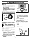
TO ADJUST STEERING WHEEL ALIGNMENT
If steering wheel crossbars are not horizontal (left to right)
when wheels are positioned straight forward, remove steer-
ing wheel and reassemble per instructions in the Assembly
section of this manual.
FRONT WHEEL TOE-IN/CAMBER
The front wheel toe-in and camber are not adjustable on
your tractor. If damage has occurred to affect the front
wheel toe-in or camber, contact your nearest authorized
service center/department.
FIG. 29
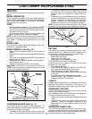
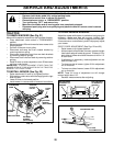
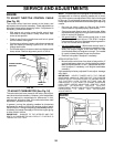
TO ADJUST ATTACHMENT CLUTCH
(See Fig. 27B)
The electric clutch should provide years of service. The
clutch has a built-in brake that stops the pulley within 5
seconds. Eventually, the internal brake will wear which
may cause the mower blades to not engage, or, to not stop
as required. Adjustments should be made by your nearest
authorized service center/department.
• Make sure attachment clutch and ignition switches are
in “OFF” position.
• Adjust the three nylon locknuts until space between
clutch plate and rotor measures .012" at all three slot
locations cut in the side of brake plate.
NOTE: After installing a new electric clutch, run tractor at
full throttle and engage and disengage electric clutch 10
cycles to wear in clutch plate.
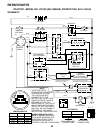
BRAKE
PLATE
NYLON
LOCKNUT (3)
FIG. 27B
CLUTCH PLATEROTOR
SLOT (3)
.012"
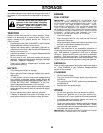
TO REPLACE MOTION DRIVE BELT
(See Fig. 28)
Park the tractor on level surface. Engage parking brake.
For assistance, there is a belt installation guide decal on
bottom side of left footrest.
• Remove mower (See “TO REMOVE MOWER” in this
section of this manual.)
CLUTCH LOCATOR
CLUTCH
WIRE
HARNESS
STATIONARY
IDLER
TRANSMISSION
INPUT PULLEY
CLUTCHING
IDLER
ELECTRIC
CLUTCH
UPPER BELT
KEEPER
LOCATOR
TABS
• Road test tractor for proper stopping distance as stated
above. Readjust if necessary. If stopping distance is
still greater than six (6) feet in highest gear, further
maintenance is necessary. Contact your nearest au-
thorized service center/department.
• Disconnect clutch wire harness.
• Remove clutch locator.
• Remove upper belt keeper.
• Remove belt from stationary idler and clutching idler.
• Pull belt slack toward rear of tractor. Carefully remove
belt upwards from transmission input pulley and over
cooling fan blades.
• Pull belt toward front of tractor and remove downwards
from around electric clutch.
• Install new belt by reversing above procedure.
IMPORTANT: MAKE SURE UPPER BELT KEEPER IS
POSITIONED PROPERLY BETWEEN LOCATOR TABS
AND ELECTRIC CLUTCH WIRE CONNECTION IS
SECURE.
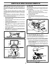
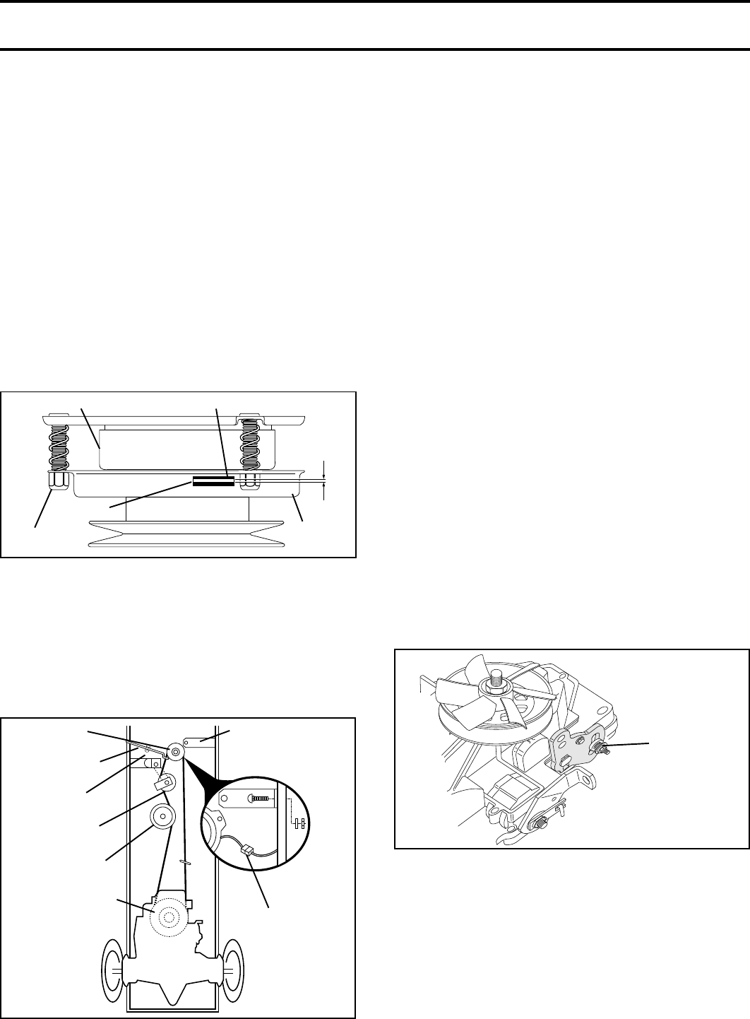
TO ADJUST MOTION CONTROL LEVER (See
Fig. 29)
The motion control lever has been preset at the factory and
adjustment should not be necessary.
If for any reason the motion control lever will not hold its
position while at a selected speed, it may be adjusted at the
friction pack located on the right side of transmission.
• Park tractor on level surface. Stop tractor by turning
ignition key to “OFF” position, and engage parking
brake.
• Adjust motion control lever by tightening adjustment
locknut one half (1/2) turn.
NOTE: If for any reason the effort to move the motion
control lever becomes too excessive, reverse the above
adjustment procedure by loosening locknut 1/4 to 1/2 turn.
Road test tractor after adjustment and repeat procedure if
necessary.
TRANSMISSION REMOVAL/REPLACEMENT
Should your transmission require removal for service or
replacement, it should be purged after reinstallation and
before operating the tractor. See “PURGE TRANSMIS-
SION” in the Operation section of this manual.
FIG. 29
ADJUSTMENT
LOCKNUT