


ASSEMBLY
8
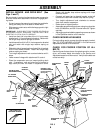
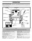
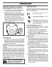
INSTALL MOWER AND DRIVE BELT (See
Figs. 5 and 7)
Be sure tractor is on level surface and mower suspension
arms are raised with attachment lift control. Engage park-
ing brake.
• Cut and remove ties securing anti-sway bar and belts.
Swing anti-sway bar to left side of mower deck.
• Slide mower under tractor with discharge guard to right
side of tractor.
IMPORTANT: CHECK BELT FOR PROPER ROUTING IN
ALL MOWER PULLEY GROOVES. INSTALL BELT INTO
ELECTRIC CLUTCH PULLEY GROOVE.
• Install one front link in top hole of the L.H. front mower
bracket and L.H. front suspension bracket. Retain with
two single loop retainer springs as shown.
• Install second front link in R.H. front suspension bracket
only and retain with single loop retainer spring as
shown.
• Slide right side of mower back and install link in top hole
of R.H. front mower bracket. Retain with single loop
retainer spring as shown.
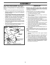
• Turn height adjustment knob counterclockwise until it
stops.
• Lower mower linkage with attachment lift control.
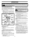
• Place the suspension arms on inward pointing deck
pins. If necessary, rock and raise front of mower to
align deck pins with the holes in suspension arms.
Retain with double loop retainer springs with loops
down as shown.
• Connect anti-sway bar to chassis bracket under left
footrest and retain with double loop retainer spring.
• Turn height adjustment knob clockwise to remove
slack from mower suspension.
• Raise deck to highest position.
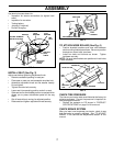
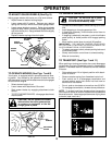
• Assemble gauge wheels as shown using long shoulder
bolts, 3/8 washers, and 3/8-16 center locknuts. Tighten
securely.
• Adjust gauge wheels before operating mower as shown
in the Operation section of this manual.
CHECK MOWER LEVELNESS
For best cutting results, mower should be properly leveled.
See “TO LEVEL MOWER HOUSING” in the Service and
Adjustments section of this manual.
CHECK FOR PROPER POSITION OF ALL
BELTS
See the figures that are shown for replacing motion, mower
drive, and mower blade drive belts in the Service and
Adjustments section of this manual. Verify that the belts are
routed correctly.
SINGLE
LOOP RETAINER
SPRINGS
SHOULDER
BOLT
ANTI-SWAY
BAR
GAUGE
WHEEL
3/8 WASHER
IDLER
PULLEY
FRONT MOWER
BRACKET
SUSPENSION
ARMS
L.H. GAUGE
WHEEL BAR
DOUBLE LOOP
RETAINER SPRING
DISCHARGE
GUARD
FRONT
SUSPENSION
BRACKETS
FRONT
LINKS
CHASSIS
BRACKET
3/8-16
CENTER
LOCKNUT
ELECTRIC
CLUTCH
PULLEY
FIG. 5
DOUBLE LOOP
RETAINER SPRING
(Inward pointing
deck pins)
USE PLIERS FOR
RETAINER SPRINGS