


SERVICE AND ADJUSTMENTS
22
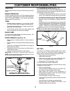
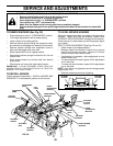
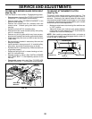
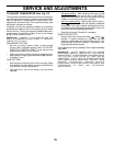
TO REPLACE MOWER BLADE DRIVE BELT
(See Fig. 25)
Park the tractor on level surface. Engage parking brake.
• Remove mower drive belt (See “TO REPLACE MOWER
DRIVE BELT” in this section of this manual).
• Remove mower (See “TO REMOVE MOWER” in this
section of this manual).
• Remove four screws from R.H. mandrel cover and
remove cover. Unhook spring from bolt on mower
housing.
• Carefully roll belt off R.H. mandrel pulley.
• Remove belt from center mandrel pulley, idler pulley,
and L.H. mandrel pulley.
• Remove any dirt or grass which may have accumu-
lated around mandrels and entire upper deck surface.
• Check secondary idler arm and idler to see that they
rotate freely.
• Be sure spring is hooked in secondary idler arm and
sway-bar bracket.
• Install new belt in lower groove of L.H. mandrel pulley,
idler pulley, and center mandrel pulley as shown.
• Roll belt over R.H. mandrel pulley. Make sure belt is in
all grooves properly.
• Reconnect spring to bolt in mower housing and rein-
stall R.H. mandrel cover.
• Reinstall mower to tractor (See “INSTALL MOWER
AND DRIVE BELT” in the Assembly section of this
manual).
• Reassemble mower drive belt (See “TO REPLACE
MOWER DRIVE BELT” in this section of this manual).
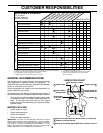
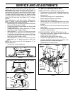
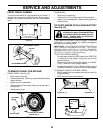
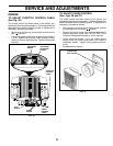
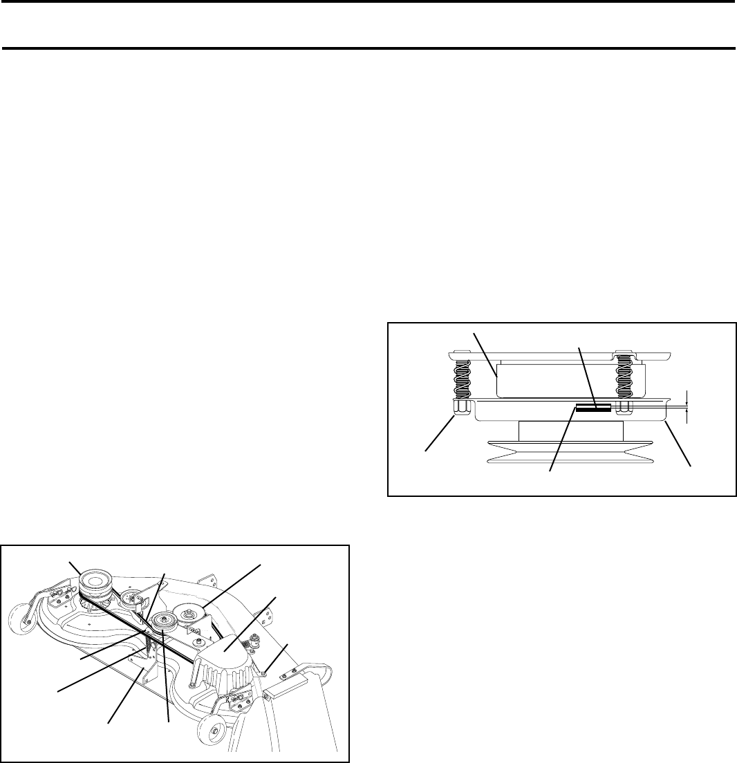
TO ADJUST ATTACHMENT CLUTCH
(See Fig. 26)
The electric clutch should provide years of service. The
clutch has a built-in brake that stops the pulley within 5
seconds. Eventually, the internal brake will wear which
may cause the mower blades to not engage, or, to not stop
as required. Adjustments should be made by your nearest
authorized service center/department.
• Make sure attachment clutch and ignition switches are
in “OFF” position.
• Adjust the three nylon locknuts until space between
clutch plate and rotor measures .012" at all three slot
locations cut in side of brake plate.
NOTE: After installing a new electric clutch, run tractor at
full throttle and engage and disengage electric clutch 10
cycles to wear in clutch plate.
ROTOR
CLUTCH PLATE
.012"
NYLON
LOCKNUT (3)
SLOT (3)
BRAKE PLATE
FIG. 26
MOWER BLADE
DRIVE BELT
R.H.
MANDREL
COVER
CENTER
MANDREL
SCREW
L.H. MANDREL
SWAY BAR
BRACKET
SPRING
SECONDARY
IDLER ARM
FIG. 25
IDLER
PULLEY