


13
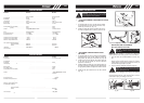
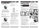
• REPLACING CUTTER LINE
1. Turn the nut (A) CLOCKWISE and remove it (Fig.
15A).
2. Remove the spool (C), and spring (D) from spindle
(E).
3. Remove any remaining cutter line.
4. Doublea32' (9.8m) length of .095 or .105" (.24 or
.27cm) cutter line. Place the looped center in one of
the slots (G) of the spool divider (Fig. 15B).
5. Wind as shown in illustration (Fig. 15C), keeping ten-
sion, with each half separated by the spool divider.
Wind to within 6" (15cm) of the ends.
6. Lock each end of line intoaslot (H) on opposite sides
of the spool (Fig. 15D).
7. Install the spring (D) over the spindle (E). Insert each
end of the linethrough an eyelet (J) in thehousing (F)
(Fig. 15E).
8. Lower the spool into the housing(E) while feeding the
line through the eyelets (J). Ensure the spring seats
itself into the spool (Fig. 15E).
9. Once the spool is in place, apply pressure on the
spool compressing the spring. Pull each end of the
line (B) sharply
to unlock the line from the slots (Fig.
15F).
10. Continue to apply pressure to the spool until the knob
can be threaded COUNTERCLOCKWISE onto the
spingle.Tighten the knob securely by hand only (Fig.
15H)
11. Trim the excess line to approximately 5” (13cm). This
wil minimize load on engine durig starting and warm-
up.(Fig. 15H)
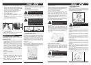
• AIR FILTER
To Clean Air Filter:
1. Remove button (A) holding air filter cover in
place,
remove cover (B) and lift filter (C) from air box
(Fig.16).
2. Wash filter in soap and water. DO NOT USE GASO-
LINE!
3. Air dry filter.
4. Reinstall filter.
NOTE: Replace filter if frayed, torn, damaged or unable to
be cleaned.
• FUEL CAP/FUEL FILTER
1. Completely remove fuel cap (A) from fuel tank (B)
to be able to remove fuel filter (D) from tank. Use a
piece of wire (C) withahook formed at the end to
pull filter out of tank. (Fig. 17A & Fig. 17B)
2. Pull filter (D) off withatwisting motion.
3. Replace
fuel filter (D). (Fig. 17C)
NOTE: Never operate the trimmer without the fuel
filter. Internal engine damage could result!
MAINTENANCE INSTRUCTIONS
A. KNOB
B. CUTTERLINE
C. SPOOL
D. SPRING
E. SPINDLE
F. HOUSING
G. DIVIDER SLOTS
H. SLOTS
J. EYELETS
A
B
C
B
G
D
E
F
J
Fig. 15A
Fig. 15B Fig.15C
Fig. 15E
Fig. 15D
Fig. 15F Fig. 15G Fig. 15H
5” (13mm)
J
E
F
D
J
B
B
H
CAUTION: NEVER operate trimmer without
the air filter.The air filter must be kept clean.
If it becomes damaged, installanew filter.
Fig. 16
B
COUTION:
Remove fuel from unit and store
in approved container before starting this
procedure. Open fuel cap slowly to release
any pressure which may have formed in fuel
tank.
14
• CARBURETOR ADJUSTMENT
The carburetor was pre-set at the factory for optimum per-
formance. If further adjustments are necessary, please
take your unit to the nearest Authorized Service Center.
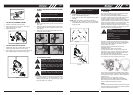
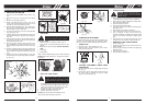
• SPARK PLUG
1. Spark plug gap = .025" (.635mm) (Fig. 18).
2. Torque to 105 to 130 inch pounds (12 to 15 N•m).
Connect spark plug boot.
• CUTTING ATTACHMEN T GUARD KNIFE
SHARPENING
1. Remove cutter knife(A) from cutting attachment guard
(B) (Fig. 19).
2. Place knife inabench vise. Sharpen knife using a flat
file, being careful to maintain the angle of cutting
edge. File in one direction only.
• STORING A UNIT
1. Perform all the general maintenance recommended
in the Maintenance Section of your User Manual.
2. Clean exterior of engine, Output Shaft, cutting attach-
ment guard and cutting head.
3. Drain fuel from the fuel tank.
4. After fuel is drained, start engine.
5. Run engine at idle until unit stops.This will purge the
carburetor of fuel.
6. Allo
w engine to cool (approx. 5 minutes).
7. Using a spark plug wrench, remove the spark plug.
8. Pour 1 teasp
oon of clean 4-cycle oil into the
combustion chamber. Pull starter rope slowly several
times to coat internal components. Replace spark
plug.
9. Store unit inacool, dry place away from any source
of ignition such as an oil burner, water heater, etc.
• REMOVING A UNIT FROM STORAGE
1. Remove spark plug.
2. Pull starter rope briskly to clear excess oil from com-
bustion chamber.
3. Clean and gap spark plug or install a new spark plug
with proper gap.
4. Prepare unit for operation.
5. Fill fuel tank with proper fuel.
Fig. 17A Fig. 17B
A
C
B
Fig. 17C
D
Fig. 18 Fig. 19
F
E
WARNING: Failure to follow these steps
may cause varnish to form in the carburetor
and difficult starting or permanent damage
following storage.
A
C
NOTE: clean the air filter element every 3 months or 25 hours.
GB GB