


8
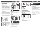
2. Install blade (C) with teeth pointing CLOCKWISE as
shown in the illustration (Fig. 6B).
3. Install flange (E) with FLAT SURFACE facing blade
(Fig. 6B).
NOTE: Make sure blade is centered on collar arbor.
4. Tighten nut (B) securely by turning it COUNTER-
CLOCKWISE with socket wrench (F). Remove hold-
ing pin (Fig. 6B).
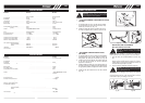
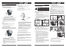
• Refueling
NOTE:
WARNING: Be sure the blade center hole is
properly sized to the collar arbor.
Fig. 6A
C
F
B
A
D
E
FUEL SYSTEM
GNINRA W :
Gasoline is highly flammable and explosive.
You can be burned or seriously injured when
handling fuel.
• Stop the engine and keep heat, sparks, and
flame away.
• Handle fuel only outdoors.
• Wipe up spills immediately.
7
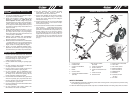
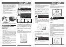
• CUTTING ATTACHMENT GUARD
2. place the guard on the cutting shaft, then install
1. Install the cutoff knife as shown below.
clamp (A)on the guard. (Fig.3 )
3. Tighten screws (B).
NOIT A LLA T SNI DAEH GNITTUC •
. 1 Install spline sleeve (D) and gear collar (A) in turn
ensuring that collar spacer is in place (Fig. 4).
otno daeh gnittuc daerht dna )C( nip gnidloh t r esnI . 2
4) . giF( ylno dnah y b daeh gnittuc nethgiT . tfahs
• REMOVE AND INSTALLATIONTHE BLADE
COVER
1. Before assembling blades, please remove the blades
cover first.
2. Refer figure 5A and Figure 5B, hold the blades cover,
and pull sligtly the cover outward the cover can be
taken apart.
3. Refer to figure 5C and 5D, and assemble in the oppo-
site way to cover the blades.
• BLADE INSTALLATION
1. To install the blade you will need the items illustrated
above (screwdriver not provided): holding pin (A),
retaining nut (B), blade (C), screwdriver (D), flange
(E), socket wrench (F) (Fig. 6A)
Fig. 2C
A
Fig. 3
B
A
B
A
D
C
Fig. 4
CAUTION: Before you take apart the blades,
wear gloves to prevent any danger.
CAUTION:When the machine is not in use or
in transportation, make sure blades have
been covered.
Fig. 5A Fig. 5B
Fig. 5C Fig.5D
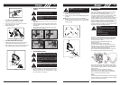
CAUTION: NEVER use unit if blade is
warped or has teeththat are chipped or miss-
ing. Replace a damaged blade immediately.
CAUTION: NEVER operate unit with a blade
unless metal blade guard is properly
installed. NEVER operate a unit withadam-
aged guard.
CAUTION: Always wear heavy-duty work
gloves when handling and installing a blade.
This engine is certified to operate on unleaded gasoline
with a pump octane rating of 93 or higher.
You may use regular unleaded gasoline containing no
more than 10% ethanol (E10) or 5% methanol by volume.
In addition, methanol must contain cosolvents and
corrosion inhibitors. Use of fuels with content of ethanol or
methanol greater than shown above may cause starting
and/or performance problems. It may also damage metal,
rubber, and plastic parts of the fuel system. Engine
damage or performance problems that result from using a
fuel with percentages of ethanol or methanol greater than
shown above are not covered by warranty.
Check the fuel level by looking through the translucent
fuel tank. If the fuel level is low, refuel in a well-ventilate d
area with the engine stopped. If the engine has been
running, allow it to cool first.
Never use stale or contaminated gasoline or an
oil/gasoline mixture.
Avoid getting dirt or water in the fuel tank.
To refuel, rest the trimmer on the ground with the fuel
tank cap facing up, as shown. Remove the fuel tank cap
and fill the tank with gasoline to the bottom of the filler
neck. Refuel carefully to avoid spilling fuel.
Do not overfill. There should be no fuel in the filler neck.
After refueling, tighten the fuel tank cap securely.
Never refuel the engine inside a building where gasoline
fumes may reach flames or sparks. Keep gasoline away
from appliance pilot lights, barbecues, electric appliances,
power tools, etc.
Spilled fuel is not only a fire hazard, it causes
environmental damage. Wipe up spills immediately.
Move at least 10 feet (3 meters) away from the fueling
source and site before starting the engine.
Fuel can damage paint and plastic. Be careful not to spill
fuel when filling your fuel tank. Damage caused by spilled
fuel is not covered under warranty.
Fig. 6B
Fig. 7A
GB GB
A
E
B
F
C