


17
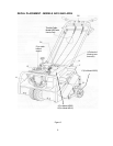
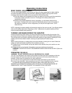
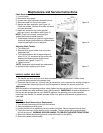
HANDLE - MODEL AR19 ONLY
Inspection
1. The handle cam lock must lock shut under moderately heavy hand pressure. Handle frame
should be tightly secured to the aerator body.
2. Check the cam rod lock nut. If it turns freely by hand when cam is released, the locking strength of
the nut has been relieved and the nut must be replaced to maintain the security of the Iock.
Adjustment
With the handle in the operating position, slowly tighten the cam rod lock nut (1/4 turn at a time) until
the cam handle locks with moderately heavy hand pressure. IMPORTANT: excessive adjustment of
the lock nut will damage the cam rod. ALWAYS replace a free spinning nut to avoid unwanted
loosening of the handle. For smooth operation of the cam, apply a small amount of grease on the
cam edge.
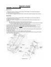
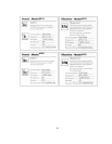
WHEELS
Drive Wheel Shaft Removal and Replacement
1. Turn off engine and empty all fuel from the fuel tank.
2. Remove weights and drive guard.
3. Loosen the Iock nut on adjustment screw to Ioosen the chain. Remove master link and chain.
4. Tip the front end up to let the aerator rest on its handle. The front wheel will be approximately 1
foot off the ground. WARNING: SECURE HANDLE TO PREVENT AERATOR FROM TIPPING.
5. Remove the wheel shaft bearing bolts (4 on the AR19 and 6 on the AR25).
6. Remove the wheel axle assembly.
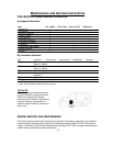
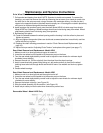
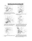
Chain Removal and Replacement
1. Turn off engine.
2. Remove the drive guard.
3. Loosen chain idler adjustment bolt and lock nut
4. Remove master link and remove chain.
5. Inspect and align sprockets. (see Figure 16).
Check set screws. (Double set screws for wheel
and rotor sprocket).
6. Install new chain from top (drive sprocket
side) and route in accordance with Figure 15.
NOTE: Chain is most easily connected just
behind the fiont drive wheel sprocket.
7. Install master link with pin plate on engine side of
chain with keeper plate installed on outboard side.
Install clip with split to front of machine.
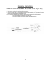
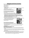
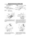
Adjusting Chain Tension
1. Turn engine off.
2. Remove drive guard, loosen lock nut on idler
adjustment bolt.
3. Turn idler adjustment bolt to adjust tension to
allow 1/8" to 1/4" movement at the center point
between the wheel sprocket and the rotor
sprocket (see Figures 15 and 17).
4. Tighten lock nut.
NOTE: Husqvarna recommends the replacement
of sprockets when replacing drive chain.
Figure 15
Figure 16
Figure 17
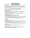
Maintenance and Service Instructions