


16
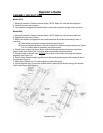
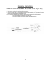
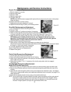
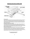
Engine, Removal and Replacement
1. Remove weights for access.
2. Remove drive guard.
3. Remove V-Belt.
4. Remove engine bolts.
5. Lift engine from unit.
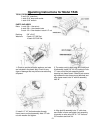
NOTE: Model AR25 aerators equipped with optional Honda engines have 2 pairs of shim plates
under the engine.
6. Remove and retain V-pulley and key.
7. Replacement procedure opposite of removal.
8. Adjust drive belt and align V-pulley, see following section.
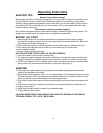
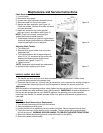
Drive Belt Replacement and Adjustment
1. Turn off engine and remove the drive guard cover.
2. Remove V-belt.
3. Inspect condition of V-pulleys and replace if necessary.
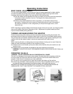
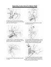
4. Check V-pulley alignment by looking down the belt with clutch engaged. Be sure both
V-pulleys are directly in line with each other. Correct their alignment if they are not.
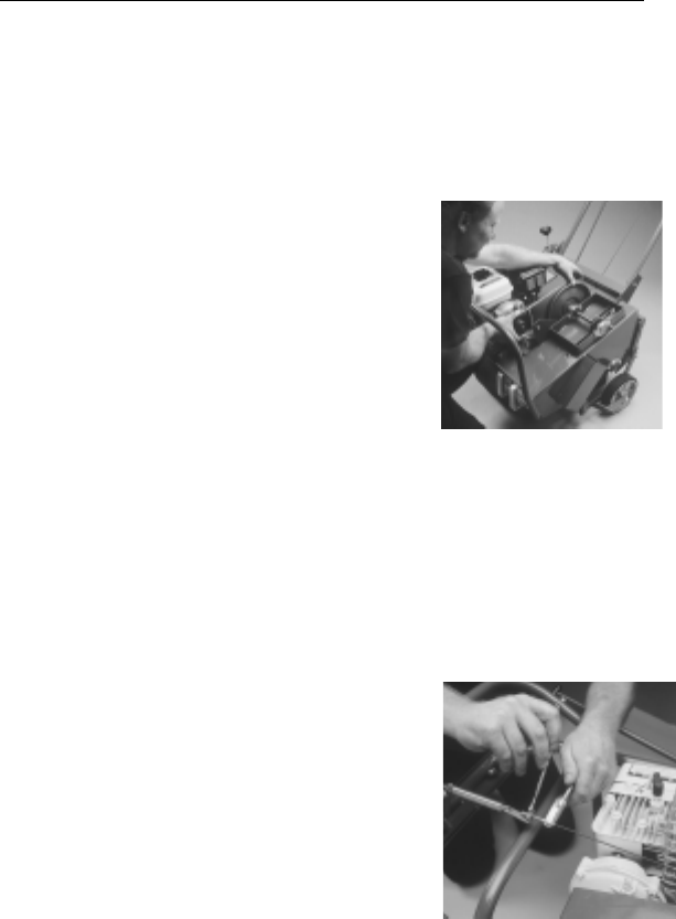
5. Install new belt over small V-pulley first, then over the large V-pulley. (see Figure 13).
NOTE: Many parts including the drive belt on your Husqvarna Aerator are made
specificlly for Husqvarna to give many hours of use. Replace all parts with genuine
Husqvarna parts to obtain maximum performance and life.
6. Insure V-belt is inside both keeper arms.
7. Check that the V-belt clears the top belt keeper arm when idler is pulled tight.
Check that the aerator rolls freely (with handle folded on Model AR19), with the belt slack. Adjust
the keeper, or clutch cable length if necessary.
8. For clutch adjustments refer to next section
(Clutch Cable Removal and Replacement).
9. Replace drive guard.
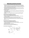
Clutch Cable Removal and Replacement
1.Turn off engine and remove old clutch cable.
2. Route new cable through the hole at the rear of housing.
3. Attach clutch cable to the bracket on the spring on the idler assembly, then connect opposite
end of cable to the S hook.
4. Adjust cable to obtain ¾” to1 ¼” extension of the clutch spring when clutch is engaged.
(see Figure 14).
Throttle Cable Removal and Replacement:
Model AR25 Honda Engine Only
1. Before removing your old cable measure the amount of cable extending past the cable screw.
2. Remove the old throttle cable and route the new cable through the guide hole at the rear of the
housing.
3. Insert the new cable through the cable screw to the measurement obtained in step 1 and tighten.
This is only an approximate setting, some additional adjustment may be required, see page 12 for
cable adjustment.
4 Attach the new adjuster bracket to the spring on the throttle/clutch lever.
NOTE: As the cable length increases between the cable screw and adjuster nut the engine speed
decreases. If engine speed is too low, the engine will stall as the clutch engages. As the
cable length decreases between the cable screw and adjuster nut, the engine speed will
increase. If engine speed is too high, the controlled start will be lost.
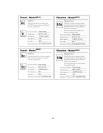
Figure 13
Figure 14
Maintenance and Service Instructions