


ASSEMBLY
Your new mower has been assembled at the factory with the exception of those parts left un-
assembled for shipping purposes. To ensure safe and proper operation of your mower, all
parts and hardware you assemble must be tightened securely. Use the correct tools as
necessary to insure proper tightness.
TOOLS REQUIRED
FOR ASSEMBLY
1. 7/16" wrench or 7/16" socket w/drive
ratchet
2. Tire pressure gauge
3. Nail bar or claw hammer
4. Wire snips
When right or left hand is mentioned in this
manual, it means when you are in the operating
position (seated) or left is trim side and right is
discharge side.
TO REMOVE THE MOWER
FROM CRATE
UNPACK CRATE
Place mower crate on fiat surface.
Using the nail bar or hammer, remove the
top of the crate first. Then remove the
sides of the crate and place these out of
the way. Be careful of any exposed nails
or staples.
Remove the plastic bag that covers the
mower.
Using the wire snips, cut any plastic ties
that are holding the mower to the crate.
Remove the seat and literature bag from
shipping position at front of the mower
and place in a safe location, near by.
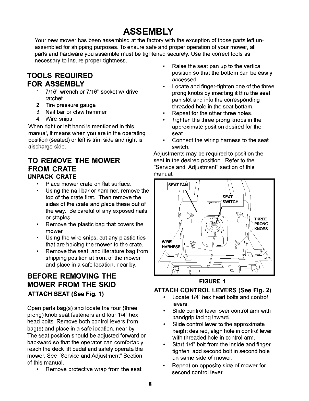
Raise the seat pan up to the vertical
position so that the bottom can be easily
accessed.
Locate and finger-tighten one of the three
prong knobs by inserting it thru the seat
pan slot and into the corresponding
threaded hole in the seat bottom.
Repeat for the other three holes.
Tighten the three prong knobs in the
approximate position desired for the
seat.
Connect the wiring harness to the seat
switch.
Adjustments may be required to position the
seat in the desired position. Refer to the
"Service and Adjustment" section of this
manual.
BEFORE REMOVING THE
MOWER FROM THE SKID
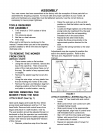
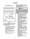
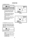
ATTACH SEAT (See Fig. 1)
Open parts bag(s) and locate the four (three
prong) knob seat fasteners and four 1/4" hex
head bolts. Remove both control levers from
bag(s) and place in a safe location, near by.
The seat position should be adjusted forward or
backward so that the operator can comfortably
reach the deck lift pedal and safely operate the
mower. See "Service and Adjustment" Section
of this manual.
Remove protective wrap from the seat.
FIGURE 1
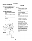
ATTACH CONTROL LEVERS (See Fig. 2)
Locate 1/4" hex head bolts and control
levers.
Slide control lever over control arm with
handgrip facing inward.
Slide control lever to the approximate
height desired, align hole in control lever
with threaded hole in control arm.
Start 1/4" bolt from the inside and finger-
tighten, add second bolt in second hole
on same side of mower.
Repeat on opposite side of mower for
second control lever.
8